The Effects of Degradation Phenomena of the Steel-Concrete Interface in Reinforced Concrete Structures ()
1. Introduction
Concrete in general, a material with a strong tendency to crack is widely used throughout the world for so-called durable constructions. In reinforced concrete structures, cracks develop particularly in areas subject to bending-type stresses (traction-compression) [1] . Also, some infrastructure soils lend themselves well to this.
Indeed, concrete resists compression well, but, in traction, it has an almost fragile behaviour and low resistance (10 times lower than that measured in compression). This is why it is associated with steel [2] . While steel reinforcements provide good mechanical strength, they do not completely prevent the appearance of cracks in concrete [3] .
Concrete cracking is characterized by the appearance of micro-cracks that can appear in the material as soon as it is installed (consequence of the phenomenon of shrinkage at a young age, for example). These micro-cracks then propagate in the structure as it is stressed. Under the effect of greater stresses, macro cracks develop and can cause the structure to collapse [4] .
Technicians and engineers in the civil engineering profession have always wondered whether the types of soil subject to tension-compression stresses are solely responsible for cracks in concrete. This question led them to examine the steel-concrete interfaces to determine if they are not also probable sources of cracking.
Numerous studies carried out by researchers have indeed shown that in the steel-concrete interfaces, complex phenomena can arise, which will lead to the ruin of the structure [5] - [13] . It is now a question of seeking to particularly locate the responsibilities of these degradation phenomena of the steel-concrete interface and the consequences in order to substantially reduce the damage that appears immediately or over time in reinforced concrete structures.
2. Literature Review
The various degradation phenomena of the steel-concrete interface are, among others the loss of adhesion between steel and concrete and the phenomenon of corrosion of the reinforcements in the concrete [14] .
2.1. Loss of Adhesion
Reinforced concrete is the result of the combination of two materials, concrete and steel. These materials have complementary properties. One resists both traction and compression while the other resists compression well but its tensile strength is low, which makes this type of concrete very strong [15] . This property in particular explains its success in the construction industry. But, the effectiveness of this association would be nothing without one particular phenomenon: the bond between steel and concrete.
When designing a reinforced concrete element, it is considered that the adhesion between the concrete and the steel is perfect because it allows, among other things, the reinforcements not to slip in the concrete. In fact, during loading, the rebars are able to slide inside the element. This is a phenomenon attributed to the difference between the elastic E module of the two materials [16] . Other aspects of mix design and concrete placement techniques can also be responsible for excessive slippage if the cover quality of the rebar is compromised [17] .
The steel-concrete bond corresponds to a physical interaction between these two different materials, the purpose of which is to ensure the transfer and continuity of forces and stresses in their contact zone [18] . It is governed by three main mechanisms: chemical adhesion, friction and rib/concrete interaction. Adhesion can be favoured or unfavourable by the difference between the Young E’s module of the two materials, the quality of the cover concrete, the workmanship and the surface condition of the steel [19] .
Young’s modulus E, according to its definition, is the ratio of the axial stress to the corresponding unit linear strain: This is Hooke’s law which is written:
(1)
with, σ: axial stress and ε: unit linear strain.
E has the dimensions of a stress in MPa and is between 2.104 and 4.104 MPa for concrete and 2.105 and 2.1.105 MPa for steel.
Degradation of the bond through slippage of the reinforcement generally involves cylindrical cracking. This must pass through one and/or the other of the two materials. Concrete has a lower Young’s modulus in compression than steel, which is an order of magnitude stiffer and stronger than concrete. This difference in modulus will have a negative influence on the bond, because these two materials (steel and concrete) do not have the same capacity to deform together as a single material [20] . Thus, bond degradation occurs only in concrete near steel.
The coating must be sufficient to guarantee good transmission of adhesion forces, good protection of the steel and suitable fire resistance.
The quality of the cover concrete is conditioned by the dosage and the vibration conditions which influence the compactness. The formulation and preparation of concrete, the methods of placing and curing must allow the concrete to develop all its qualities [21] .
Bars with surfaces showing irregularities or roughness (roughness, relief) are characterized by very high adhesion (2 to 3 times greater than that of smooth round steels (RL)). They achieve 70% to 75% of the total bond strength [22] . Equation (3) allowed us to calculate the bond stress noted τsu. In Table 1, we have presented a comparative example of the bond stresses of HA and RL steels for a compressive strength of concrete at 28 days equal to 25 MPa.
![]()
Table 1. Comparison of bond stresses τsu between HA and RL steels.
In addition, it should be remembered that τsu due to shrinkage deformations generally presents 10% to 15% of the total adhesion resistance. As for τsu due to the bonding of cement to steel, it is of the order of 0.2 to 0.5 MPa [23] .
2.2. The Corrosion Phenomenon
In the case of reinforced concrete structures, the resistance of steels to corrosion is the main factor to be taken into account when studying the durability of different types of structures. Corrosion of reinforcements is the cause of about 80% of the degradation of these types of structures and works [24] . Their lifespan is conditioned by the response to physical and chemical attacks from the environment, as well as by the ability of the constituent materials to protect themselves against these attacks [25] . To this end, it is very important to know the corrosion process and its environmental and structural interactions.
Corrosion will develop mainly according to two processes: slow and uniform carbonation of the concrete along the reinforcement and attack by chlorides which, when they are in sufficient quantity around the reinforcement, generate pitting of corrosion [26] . This process is rapid in terms of kinetics and highly localized. When corrosion becomes active, the mechanical behaviour of the structure changes. This is mainly due to the reduction in the section of corroded reinforcement which can lead to a reduction in the mechanical resistance thereof. The volume of corroded steel is significantly greater than that of sound steel. This volumetric increase generates pressure on the concrete and thus cracks or bursting of the cover concrete [27] [28] [29] [30] . Over the past two decades, much research has been done on the corrosion of reinforcement in concrete with the aim of predicting its influence [31] [32] [33] [34] [35] . The effects and consequences of corrosion are diverse and can be represented by the diagram in Figure 1 [36] .
The causes of corrosion are multiple and complex and they result from chemical
![]()
Figure 1. Effects of corrosion on the mechanical behaviour of corroded structures.
and/or physical interactions between the material and its environment. Corrosion phenomena therefore depend on the material and the surrounding environment.
The different parameters that promote the corrosion of a material are: Chemical composition and microstructure of the metal, chemical composition of the environment, physical parameters (temperature, irradiation, etc.) and mechanical stresses (stresses, shocks, friction, etc.) [37] .
The different types of corrosion are: Chemical corrosion; biochemical corrosion and electrochemical corrosion [38] [39] . As a general rule, it is considered that corrosion can only take place when aggressive agents have penetrated the cover concrete and reached the reinforcement.
3. Material and Methods
3.1. Material
We give a brief overview of the materials used for this study. These are ordinary concrete used in the construction of buildings and general works with a density varying between 2.0 and 2.5 t/m3, high adhesion steel (HA) and steel-concrete interface.
3.1.1. Concrete
Concrete, the physical properties of which are given in Table 2 below, is an artificial stone obtained from a correctly dosed mixture (that is to say in well-determined proportions) of binder, water, aggregates (large and small) and possibly additives. This mixture, when wet, is called fresh concrete. After hydration, it hardens to give a very resistant stone called concrete. It is mainly used for its resistance in compression.
According to Table 3 below, in a volume of concrete, the different components are in different proportions.
The characteristic strengths of concrete are: compressive strength fc28 (main characteristic determined by a standardized laboratory test); the tensile strength
![]()
Table 2. Physical properties of concrete.
![]()
Table 3. Proportions of the different components of concrete.
ft28 and the shear (sliding) strength τbj.
During its hardening, the concrete takes, little by little, its resistance and at the end of the 28th day, this resistance reaches its characteristic value, designating the class of concrete. The resistance of concrete increases according to a logarithmic law of formula (2) below:
(2)
where, j is the age of the concrete, in days (d ≤ 28 days) and fc28 is the strength of the concrete at 28 days of age, expressed in MPa.
The characteristic compressive strength of concrete at age “j”, when “j” is very large, can be determined by the following formula (3):
for
(3)
The tensile strength of concrete (ftj) is determined by relation (4) below:
(4)
For calculations in RC, the tensile strength of concrete is neglected.
The shear strength
is calculated by formula (5) below:
(5)
where, kc = (1.5 - 2.0) is a coefficient depending on the class of the concrete.
The deformations of concrete are: shrinkage (of the order of 5 × 10⁻⁴), swelling (often neglected) and creep.
3.1.2. Steel
Considered as a reinforcing element, steel is an alloy of iron (approximately 98%) and carbon (up to 2.0%) containing a very low percentage of impurities (originating from mining or formed during manufacturing) as well as adjuvant (up to 10% sometimes) to improve its qualities [40] .
The steels used in reinforced concrete structures are: smooth rounds (RL, in French), which have no roughness on the surface and high adhesion steels (HA), having roughness to improve the steel-concrete adhesion. Concrete steels have different grades which correspond to their qualities of elasticity limit (varies between 200 and 500 MPa) and resistance [41] .
The density of steel is 7.85 t/m3 (2 to 3 times greater than that of concrete). Thanks to its high mechanical resistance, it is considered the lightest construction material (2 times lighter than wood and 10 times lighter than ordinary concrete). Its coefficient of thermal conductivity is 58.35 W/m∙˚C (40 times that of concrete). At 200˚C, its modulus of elasticity E decreases and at 600˚C already, it changes to the plastic state [42] .
The main mechanical characteristics of steel are its mechanical resistance and its deformability, which depend on its composition and the technology of its manufacture. The strain diagrams of steel in tension and in compression are identical; they are symmetrical with respect to the origin O. These diagrams make it possible to determine the mechanical characteristics of steels (the elastic limit Fe and the resistance limit Frup), the characteristic unit strains of elasticity
, of rupture
and the modulus of elasticity E [43] .
3.1.3. Steel-Concrete Interface
In general, a load-bearing reinforced concrete element is a complex system made up of several components (concrete, steel, and interface) whose behaviours are very different from each other. The behaviour of the structure depends essentially not only on the behaviour of concrete and steel but also on that of the steel-concrete interface.
By definition, the interface can be considered to be an area of concrete that surrounds the steel, and which does not a priori have any specified shape. Its shape depends directly on that of steel. The behaviour of the interface is represented by the adhesion which is a complex phenomenon and makes it possible to ensure a bond between two surfaces in contact and to transmit a stress exerted according to the contact surface of the two materials.
In the sense of reinforced concrete, once the concrete is subjected to external loads, the loading of the reinforcements is necessary for the normal functioning of the structure. Thus, this role is performed by the interface. The latter must allow total transmission of forces without slipping of the reinforcements in the concrete sheath before its deterioration. Once the deterioration of the interface has taken place, it causes a loss of adhesion which then leads to a change in the behaviour of steel and concrete [44] . It is therefore necessary to have a good understanding of the behaviour of the interface during structural calculations and during the execution of the work.
The investigation of the behaviour of the interface presented by Lutz and Gergely made it possible to conclude that the transmission of the force between the concrete and the steel takes place by the action of the following three physical phenomena: A physicochemical adhesion, directly linked to the composition of each of them and the way they are set up; a mechanical interaction, this mechanical action is particularly due to the presence of ribs along the reinforcing RCr and friction between the two contact surfaces [45] . These physical phenomena depend on various parameters: the dimensions of the structure, the nature of concrete, reinforcement and its characteristics [46] .
For ribbed steels, mechanical interaction is the main mechanism governing the behaviour of the interface. On the contrary, physic-chemical adhesion and friction are the mechanisms which dominate the behaviour of the interface in the case of smooth steels [47] [48] [49] [50] . Under the action of these physical phenomena and according to Caquot’s theory, two types of stresses can develop at the interface: Shear stresses generated by sliding along the axis of the RCr. If the axial force increases, these stresses can cause the concrete to break along conical surfaces inclined at an angle of 45˚ with the axis of the RCr and radial stresses perpendicular to the axis of the RCr (Perchat [51] , Tepfers [52] , Tilantera and Rechardt [53] ). The essential value characterizing the steel-concrete bond is its shear strength. This data makes it possible to determine the resistance of a steel cast in concrete, as well as to define an anchoring length necessary to maintain the link. The ultimate adhesion stress fbd, also called τmax in work relating to adhesion (Equation (5)), is calculated experimentally according to the following expression:
(6)
with, Fmax: maximum force obtained experimentally;
: diameter of the steeland; lb: length anchored in the concrete.
The regulatory ultimate limit value of the adhesion stress is noted τsu and is valid according to the BAEL 91 rules:
(7)
φs: The sealing coefficient relating to steel (equal to 1.5 for HA and 1 for RL).
For HA reinforcements, the calculation value of the ultimate bond strength fbd can be taken according to Eurocode 2, part 8.4.2 equal to:
(8)
with, n1 is a coefficient linked to the conditions of adhesion: n1 = 1, when the conditions of adhesion are “good” and n1 = 0.7 in the other cases; n2 is a coefficient linked to the diameter of the RCr and is equal to the max ((1.32 – φ)/100; 1); fctd: the design tensile strength of concrete as indicated in EC2 in part 3.1.6 [54] .
As a reminder, the tests which make it possible to study the behaviour of the steel-concrete interface are: The pull-out type test or pull-out test, the push-in type test and the double tie rod [55] .
The intrinsic behaviour of the interface at the local level is influenced by various external factors and parameters (limiting conditions, loads, sizing) and/or internal parameters (characteristics of materials: concrete, steel, adhesion). These parameters can occur at several scales and at different stages of interface degradation.
According to several documentary studies, the main parameters that influence the behaviour of the interface are: The geometrical characteristics of the steel, the characteristics of the concrete, the type of loading and the confinement. Other so-called secondary parameters are: Concrete placement, corrosion and age of concrete [56] [57] [58] [59] [60] .
When we talk about the cracking of reinforced concrete, we must necessarily talk about the degradation of the steel-concrete bond, since this one produces radial micro-cracks which can evolve towards different failure mechanisms, and in certain cases, they will be able to cause the fall of the resistance of the integrated system of the three components: steel-bond-concrete. Depending on these three components, failure can occur: either in concrete (longitudinal cracks), or in steel (plasticization of the reinforcement), or in the connection (cylindrical cracks) [61] .
3.2. Methods
Some accidents in reinforced concrete structures have unexplained causes when you can be sure that they do not come from the constituents and composition of the concrete, nor from the quality of the steel and the bearing capacity of the sub-floors.
Degradation in the steel-concrete interfaces is one explanatory approach. Experimentally, the type of degradation by corrosion of these interfaces, the consequences of which are on the one hand the initiation and propagation of cracks in the concrete by swelling of the rust and on the other hand, the weakening of the limit to the rupture of reinforcements by reduction of the sections of corroded high-adhesion steels. In this part of the study, we present a method for evaluating the rate of degradation of the steel-concrete interface by corrosion to assess the bearing capacity of a structural element.
3.2.1. Study Samples
To show the corrosion degradation of High Adhesion (HA) steel reinforcements, we cut out pieces of steel of about 30 cm that were attacked by rust. They were taken from reinforced concrete posts and beams intended for waste reception or recycling (Figure 2). The diameters of these uncorroded samples are respectively, from left to right, 6 mm, 8 mm and 12 mm (Figure 3).
![]()
Figure 2. Samples of the reinforcements taken showing a layer of rust.
![]()
Figure 3. Standard uncorroded reinforcements in HA steel.
3.2.2. Work Equipment
The study was conducted at the Civil Engineering Laboratory of the National High School of Public Works (NHSPW) in N’Djamena, Chad. The latitude, longitude and altitude are respectively 12.132965; 15.0540224 and 298 meters. According to the Google Maps application, consulted on April 25, 2018 at 10:00 a.m., the coordinates of the site are: 12˚07'58.7"N 15˚03'14.5"E.
Samples should be cleaned using the drill hammer, half-round, medium-sized file and wire brush. Indeed, the hacksaw is used to cut steels into pieces of about 30 cm each; the pitting hammer removes the surface layer of rust; the medium-soft file is used to remove the resistant layer of rust; the wire brush, to clean the sample and the calliper, to measure the diameter of steels with the surface layer of rust and without this layer.
3.2.3. Work Performed
1) Sample collection
For our work, we took samples from all sources, the origin and age of which we do not know, since they were taken from broken load-bearing structures intended for the recycling center. The objective here is to determine the impact of corrosion on steel and therefore on its ability to resist, the rate of reduction of which could be assessed.
2) Measurement of the rough rusty section
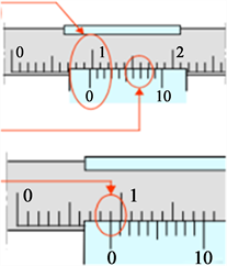
The samples being well cleaned, it is a question of measuring the new diameters of the parts most affected by corrosion using the calliper. You will first need to know how to read the measurements made with a calliper. The reading example is given below.
Vernier scale 1/10th
a) The zero of the vernier is opposite a graduation of the ruler.
Read on the ruler the number of mm before the zero of the vernier; here 9 mm.
b) The zero of the vernier is not opposite a graduation of the ruler.
Locate the vernier scale, tenths of an mm, which is best aligned, here 0.60 mm.
We finally read: 9 + 0.60 = 9.60 mm.
3) Removal of the rust layer
With the pitting hammer, we had to tap on the rusty sample to remove all the rusty layer, then we filed down the resistant layers of the rust with the medium-soft file and finally we used the wire brush to clean sample. Thus, we have samples of which the parts most affected by corrosion are revealed to be measured with the calliper.
4) Measurement of the net section most affected by rust
Using the caliper, the most damaged (degraded) sections are measured, as it is this section that is considered to be the least resistant part during a bending force of the structure, for example. These operations are presented in Figure 4 for HA6, Figure 5 for HA8 and Figure 6 for HA 12. All measured values are grouped in Table 4.
![]()
Figure 4. Operation to obtain the net section remaining after the corrosion of HA6.
![]()
Figure 5. Operation to obtain the net section remaining after the corrosion of HA8.
5) Calculation of the corrosion rate (Tc)
It is defined by the following formula [62] :
(9)
with,
is the uncorroded diameter and
is the corroded diameter
6) Modelling of degradation
Wagner’s theory of oxidation kinetics (Equation 10) was used to model the progression of the corrosion layer over time (Figure 7). Considering the constant k = 0.2, we could theoretically plot the Wagner function under Matlab.
(10)
with, Y: oxide thickness in µm; t: time in s and k: kinetic constant in µm/s1/2.
The oxide curve progresses and stabilizes after a while, limited by an asymptote
![]()
Figure 6. Operation to obtain the net section remaining after the corrosion of HA12.
![]()
Figure 7. Progression of the corrosion layer.
defined by the maximum thickness. This is because the oxide layer behaves after a while, like a shield for steel.
4. Results and Discussion
4.1. Corrosion Rate (Tc)
The results of Table 4 show that the corrosion rate is higher when the diameter of the reinforcements decreases. This fact influences the progression of the corrosion layer over time of Wagner’s theory of oxidation kinetics which was used to model corrosion degradation (Figure 7). Indeed, this study shows through experimentation that two reinforcements of different diameters
made of high-adhesion steel used in the same environmental conditions and stresses do not degrade in the same way by corrosion. The difference between the uncorroded diameter and the corroded diameter which represents the thickness of oxides in µm at a given time t varies depending on the diameter of the reinforcement. It is more important for
than for
. In Figure 7, we should plot the progression curves of the corrosion layer by diameter of reinforcement so that the curve C1 for the diameter
is greater than the curve C2 for the diameter
. In addition, as the rate of degradation is an inversely proportional function of the uncorroded diameter, it is quite justified that the rate of corrosion of
is higher than that of
.
Through this reality, we can safely accept that Wagner’s model fits well with the experimental results of our study and as an example, consider the following application to show its interest.
A theoretical section of HA steel reinforcement for the reinforcement of a structural element has been calculated and is equal to Asth = 1.08 cm2. Compared to the choice of reinforcements to reinforce this element, we have four possibilities: 4HA6 which gives a section of 1.13 cm2; 3HA8 - 1.51 cm2; 2HA10 - 1.57 cm2 and 1HA12 - 1.13 cm2. Considering the unit prices of reinforcements in the city of N’Djamena for example, 1HA6 costs 1500 Fcfa, 1HA8 - 3500 Fcfa; 1HA10 - 4500 Fcfa and 1HA12 - 6500 Fcfa, the economical choice of a real section of Acre reinforcement ≥ Asth = 1.08 cm2 will be made between 4HA6 and 1HA12 for which the real section is 1.13 cm2. The untrained designer will simply choose 4HA6 to the detriment of an HA12. However, the corrosion rate of an HA12 is low compared to that of an HA6. This example of an RC choice of the real section of reinforcement often made by some designers is a shame for a structural element because according to the previous revelations, a reinforcement of
![]()
Table 4. Average values of the corrosion rates of the samples taken.
large diameter corrodes less quickly than that of small diameter, and in more, according to paragraph 4.2, a low corrosion rate is synonymous with a less important loss of the tensile strength of the steel.
4.2. Study of the Response of a Corroded Structural Element under Mechanical Loading
A simplified approach to the bearing capacity of structural elements (including HA10 steel reinforcements) as a function of the progress of the corrosion phenomenon was proposed by Mangat and Elgalf and will serve as an RCsis for interpreting the results of our work [63] . Steel admits the constitutive law proposed by Ouglova, which accounts for embrittlement due to corrosion [64] . The loss of steel section has been explicitly taken into account. Swelling could not be considered in this study, although it was essential to assess its impact on the initiation and propagation of cracks in concrete. The results presented in Figure 8, specific to Mangat and Elgalf, will be used to assess the behavioural impacts of degradation by corrosion of the HA steel reinforcements that we have sampled and studied. This proposed approach makes it possible to satisfactorily estimate the bearing capacity according to the corrosion level of samples such as those of Almussalam et al. 1996; Castel, 2001, etc.
We are aware that in an RC structure, the load-bearing capacity is generally relative to a load-bearing element of the structure such as column, beam, etc. and essentially depends on the ultimate strengths of the two components steel and concrete. Considering the assumption of the BAEL 91 mod.99 recalled in sub-paragraph 3.1.1, according to which the tensile strength of concrete is negligible, therefore, the bearing capacity of an element subjected to tensile or bending stresses will depend only on the steel, therefore of its ultimate resistance. This is why we use the diagram of Effort (in N)-Deflection (in mm) of the steel
![]()
Figure 8. Results obtained for the beams tested by (Mangat and Elgalf, 1999)—simplified approach.
(Figure 8) to designate the bearing capacity or ultimate resistance to breaking or even ultimate resistance of an element structural feature mentioned in this study.
4.2.1. HA6 Steel Reinforcement Sample
Sample HA6 is a 30 cm section of high-tack steel 6mm in diameter (Figure 2) which has been corroded (Figure 3). The entire rust layer was removed and the new diameter of the most degraded part could be measured with a calliper (Figure 4). The value read is 3 mm. Formula (9) above made it possible to calculate a corrosion rate of 50% reported in Table 4.
In Figure 8 established by Mangat and Elgalf, which gives the different behavioural curves of HA10 steels with various experimental and numerical corrosion rates, we notice that for a corrosion rate of 7.5%, the load-carrying capacity at break dropped by half (1/2) for a deflection of about 3 mm. This implies that for a corrosion rate of 50% determined on the HA6, the ultimate limit can be assumed to be negligible (i.e. the loss of the initial bearing capacity of the steel is considered equal to 100%, i.e. 4/4 of the initial ultimate resistance). Therefore, a column or beam having reinforcement with such a corrosion rate runs a great risk of bending failure.
4.2.2. HA8 Steel Reinforcement Sample
Applying the same reasoning for the HA6 steel reinforcement sample and considering a corrosion rate for the HA8 sample (Figure 5) equal to 23.75%, the ultimate strength of this steel will decrease significantly by at most ¾ of its initial ultimate strength with even higher risks of rupture for the reinforcements and therefore for the reinforced concrete.
4.2.3. HA12 Steel Reinforcement Sample
Applying the same reasoning for the third HA12 sample (Figure 6) with a corrosion rate of 5%, the ultimate strength of this corroded steel will decrease by at most 1/4 of its initial ultimate strength.
By a logarithmic regression of the data RC on the results of this study, the trend curve of the loss of the bearing capacity as a function of the corrosion rate is presented in Figure 9. Above 50% corrosion rate, we can consider that the steel reinforcements no longer contribute to the resistance of an element of the structure. It emerges from this work that the corrosion rate of reinforcement is low when its nominal diameter is large and that the loss of the bearing capacity of a structural element is important when the corrosion rate is high.
Thus, the mathematical model of the loss of bearing capacity as a function of the corrosion rate can be written as below (11):
(11)
with, Y: the loss of bearing capacity as a fraction of the initial ultimate strength of the steel considered; ln: Natural logarithm and x: the corrosion rate in%.
Note that the coefficient of determination R2 = 0.9714 is close to 1.
In short, the loss of the bearing capacity of a structural member is an increasing
![]()
Figure 9. Trend curve for loss of bearing.
function of the rate of corrosion degradation. However, the study also shows that corrosion degradation rates are high for small reinforcement diameters. So, to guarantee a long-lasting life for a reinforced concrete structure, this study shows that we must avoid the excessive use of small diameter reinforcements. Also, this study shows that for a rational and durable operation of a complex steel-concrete element, it is not only necessary to avoid the corrosion of the steel in the concrete but it is also necessary an irreproachable adhesion allowing a good transmission of forces between concrete and steel.
Finally, at a given moment in the state of corrosion of the reinforcements in the concrete, when the tensile or bending stresses are greater than the bearing capacity or design limit resistance of an element of the structure, the cracks appears and the rupture is evident.
4.2.4. Limitation of the Experimental Study
According to the diagram of Figure 1, we want to specify that the present study relates exclusively to the loss of the steel section at the local level by corrosion to estimate the reduction in the bearing capacity at the general level. To this end, the studies of the degradation of the interface by corrosion (cause of the loss of adhesion) and of the volumetric expansion by corrosion (cause of the disappearance of the ribs) which was briefly approached and which was not developed during this experiment is the subject of studies in perspective.
During the experiment, we found that at any given time t, the progression of the corrosion layer varied depending on the diameters of the reinforcement samples tested. Normally, according to our understanding, two reinforcements of different diameters made of the same high adhesion material, used under the same environmental and stress conditions must corrode in the same way therefore have an equal thickness of the corrosion layer. We were unable to identify this contradiction and believe that this is certainly due to the multitude and complexity of certain causes of corrosion announced in paragraph 2.2.
5. Conclusions
We have focused this work on part of the effects of degradation phenomena of the steel-concrete interfaces which, it should be remembered, are physical and chemical. The experimental work was exclusively carried out on the consequences of chemical degradation by the corrosion of steel in concrete. To this end, it was first necessary to recall the degradation phenomena of the loss of adhesion between steel and concrete and the phenomenon of corrosion of steel in concrete. The second step is to notify the composition of this interface by defining the components that are concrete and steel with their different properties to highlight any incompatibility problem between these two materials. The essential concepts related to the behaviour of the steel-concrete interface were also discussed. Subsequently, it was ultimately on chemical degradation, namely corrosion by loss of steel section, that work was carried out to assess their impact on the weakening of reinforced concrete structures.
Thus, several samples were taken of corroded high adhesion steels with initial diameters HA6, HA8 and HA12. The layers of rust were carefully removed and the deeply cut diameters were measured. After calculating the corrosion degradation rate, this work reveals two important pieces of information:
· From experience, the smaller the nominal diameter of the steel reinforcement, the higher the corrosion rate.
· RC on the work of Mangat and Elgalf, we can say that the higher the corrosion rate of HA steel reinforcement, the greater the loss of its ultimate limit.