1. Introduction
Based on stability and strength of the subway tunnel and by instrument stability is a measure of confidence in the estimates. The initial cost of the used instruments, always look for a way to get the most information with the least utility. Deformation Measurements Instruments are installed in the tunnel roof and at selected points along the tunnel walls to monitor vertical, horizontal, and longitudinal in tunnel direction deformation components. The number of points and their detailed location depends on the size of the tunnel and the excavation sequencing in multiple drift applications. Also, as a minimum of the wall for each drift including temporary elements should be equipped with a device capable of measuring deformations [1] .
The designer of geotechnical construction works with naturally occurring materials, and does not find their exact engineering properties. He may carry out tests in the laboratory on the samples picked up from the field, and sometimes change the naturally occurring materials to make them more suitable for his needs. Instrumentation is used to measure the response (deformation, stress and etc.) of soil or rock to changes in loading or support arrangements, and from the measurements taken, the need for modifications to the loading or support arrangements is determined. This illustrates the basic reason why instrumentation is generally of immense value during geotechnical construction [2] .
2. Fundamentals of Instrumentation
A good instrumentation program should have one or more of the following purposes in mind such as site investigation which instruments are used to characterize and determine initial site conditions. Common parameters of interest in a site investigation are pore pressure, permeability of soil, slope stability etc. In other side, design verification based on instruments are used to verify design assumptions. Instrumentation data from the initial stage of a project may show the need or provide the opportunity to modify the design in later stages. In this process Construction Control are instruments which installed to monitor the effects of construction. Instrument data helps the engineer to determine how fast construction can proceed without adverse effects on the foundation soil and construction materials used.
Safety of instruments can provide early warning of impending failure. In case of metro railway tunnels instruments provide early warning through real time monitoring systems available on the internet for any excessive and undue ground movements affecting the adjoining premises, structure and utilities like the railways, power lines, water lines etc. In this side, legal protection based on instruments provide designers and contractors the basis of a legal defence should resident and owners of adjacent properties blame construction for damage to their property and life. This aspect gains prominence in constructions in populated areas such as for underground metro railways.
Instrument performance is used to monitor the in-service performance of a structure. For example, monitoring leakage, pore water pressure and deformation can provide an indication of the performance of a dam. Monitoring loads on rock bolts and movements within a tunnel can provide an indication of the stability of tunnel [3] [4] .
3. Test Methods for Underground Structures
3.1. In Situ Stress
In situ tests are used to directly obtain field measurements of useful soil and rock engineering properties. In soil, in situ testing include both index type tests, such as the Standard Penetration Test (SPT) and tests that determine the physical properties of the ground, such as shear strength from cone penetration Tests (CPT) and ground deformation properties from pressure meter tests (PMT). One significant property of interest in rock is it’s in situ stress condition. Horizontal stresses of geological origin are often locked within the rock masses, resulted in a stress ratio (K) often higher than the number predicted by elastic theory.
3.2. Hydraulic Fracturing
Typically conducted in vertical boreholes. A short segment of the hole is sealed off using a straddle packer. This is followed by the pressurization by pumping in water. The pressure is raised until the rock surrounding the hole fails in tension at a critical pressure.
Flat Jack Test
Like all other stress measuring methods, the flat jack method is also based on certain assumptions such as 1) the stress at the test site is compressive, 2) the surrounding rock mass is homogeneous, elastic and isotropic, 3) the rock deforms symmetrically around the slot, 4) the state of stresses at the measurement site is uniform, and 5) the stress applied to the rock by the flat jack is uniform. The method can be used only in the walls of the underground opening after the opening has been made, and measures the induced stresses from which the in situ stresses are calculated. Flat jack, the Following breakdown, the shut-in pressure, and the lowest test-interval pressure at which the hydrocrack closes completely under the action of the stress acting normal to the hydro fractures. In a vertical test hole the hydro fractures are expected to be formed in vertical and perpendicular to the minimum horizontal stress )Figure 1(.
Some Common Mistakes form-meter, reference pins, a standard distance bar and a hydraulic pump with pressure gauges are the main items of equipment required for the test. Flat jack is inserted into the slot, cemented in place, and pressurized.
When the pins have been returned to the initial separation, the pressure in jack approximates the initial stress normal to the jack. The slot cut in the horizontal direction yields induced stress tangential to the boundary of the opening and the slot cut in the vertical direction yields induced stress, parallel to the axis of the opening, at the respective slot locations (Figure 2) [6] .
ln actual tests, the length of the slot may be bigger than the jack, and the slot may not be of fixed width. Further, the stress acting in the plane parallel to the major axis of the slot also affects the contraction of the slot. The formulae given below account for the effect of all the above and can be used for evaluating the stresses (Equations (1) and (2)) [7] .
 (For jack position horizontal) (1)
 (For jack position vertical) (2)
4. Modulus of Deformation
Modulus of deformation is recognized as one of the important parameters governing the rock mass behavior. It is experienced that tunnel sections generally take long time to stabilize. These time-dependent deformation effect the tunnel lining along with the modulus of deformation of the rock mass. The study suggests that time for ninety per cent tunnel closure and deformation is less both for good quality rock and larger span of tunnel. The concept of retarded creep appears to be valid for weak and dry rock masses around a supported tunnel in non-squeezing condition. The important various tests include [8] :
4.1. Pressure Meter Test (PMT)
Where P is the flat jack cancellation pressure, Pθ is the induced stress tangential to the boundary of the opening and Pн is the induced stress parallel to the axis of the opening. K1, K2 and K3 are constants which are determined from parameters such as the length of the jack, slot dimensions, distance between reference pins, etc. Induced stresses Pθ and PH can be determined by solving simultaneous Equations (1) and (2). At each test site, several tests should be carried out to obtain statistically viable results. Typical stress-deformation plots from flat jack test data for very good quality basalt and poor quality volcanic breccia rock mass from Koyna H.E. Project, Maharashtra, with EM values of 62.8 GPa and 4.80 GPa, respectively, are shown in (Figure 3).
This test is performed with a cylindrical probe placed at the desired depth in a borehole. The Menard type pressure meter requires pre-drilling of the borehole; the self-boring type pressure meter advances the whole itself, thus reducing soil disturbance. The PENCEL pressure meter can be set in place by pressing it to the test depth or by direct driving from ground surface or from within a predrilled borehole. The hollow center PENCEL probe can be used in series with the static cone penetrometer.
The pressure required expanding the cylindrical membrane to a certain volume or radial strain is recorded in a borehole. It is applicable for soft rocks. Pressure meter are two types of High pressure instrument and Low pressure instrument (Figure 4) [9] .
The pressure meter test is an in-situ testing method which is commonly used to achieve a quick and easy
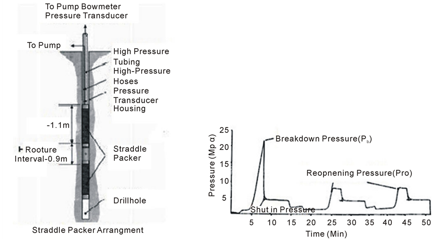
Figure 1. Schematic diagram and graphs of typical hydraulic fracturing system.


Figure 2. Slots made by jack hammer drilling and convergence measurement by deform-meter.
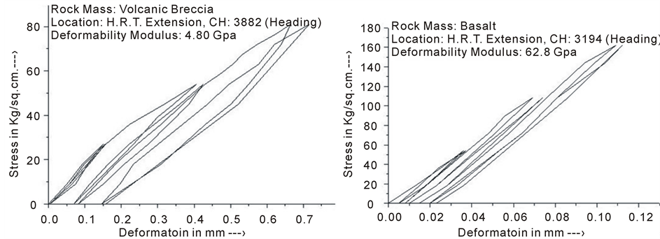
Figure 3. Typical stress verses deformation envelopes from flat jack tests.
measure of the in-situ stress-strain relationship of the soil which provides parameters such as the elastic modulus gives typical tests results (Figure 5). From the pressure strain curves, the untrained shear strength, the soil shear modulus and the in-situ horizontal stress can be obtained. On completion of a test, the cone is advanced to the
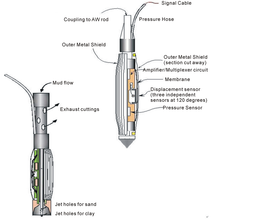
Figure 4. Low pressure instrument and high pressure instrument.
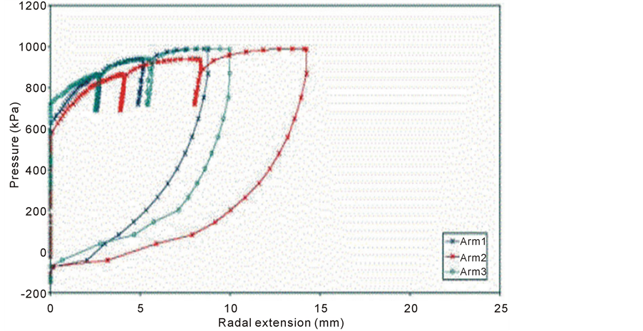
Figure 5. Typical results for a cone pressure meter test.
next test depth [10] [11] .
4.2. Figures and Tables
In addition the pressure meter membrane can be inflated to a large radial strain, approximately 50%, to ensure that the pressure meter limit pressure is approached at full inflation. The speed of cone penetration testing enables the cone pressure meter to be an economical alternative to conventional self-boring and Menard-type pressure meter tests.
4.3. Plate Bearing Test
A relatively flat rock surface us sculptured and level with mortar to receive circular bearing plates 20 to 40 inches in diameter. Loading a rock surface and monitoring the resulting displacement. This is easily arranged in the underground gallery. The site may be selected carefully to exclude loose, highly fractured rock. The modulus of subgrade reaction is calculated from the relation [12] .

5. Measuring Displacements
The objectives of ground deformation monitoring are different in mountain and urban tunnels. In mountain tunnels, the main objective of deformation measurements during construction is to ensure that ground pressures are adequately controlled, i.e., there exists an adequate margin of safety against collapse, including roof collapse, bottom heave, failure of the excavation face, yielding of the support system, etc. Adequate control of ground pressures ensures a safe and economical structure, well adapted to the inherent heterogeneity of ground conditions. As a result of these differences in objectives, design philosophies, and construction techniques, the types and required accuracy of the measured ground deformations vary between the two classes of tunnels, as follows [13] :
One ft2 Plate is placed on a soil surfacee. A load P is placed on the plate and the settlementis measured as a function of P. Two different types of shapes can be developed depending on the density of the soil. From this, we can get a peak and residual bearing capacity. Notice the shape of the curves; they look a lot like the curves seen in a direct shear test. This is because the direct shear test reflects the conditions at failure (Figure 6).
1) In mountain tunnels, considerable ground deformations are deliberately permitted (and often provoked) in order to reduce the initially very large “geostatic” loads on the temporary support by increasing ground de-confinement.
2) In urban tunnels, the main objective is limiting ground deformations around the tunnel and thus causing the minimum possible movement and disturbance at ground surface and the structures founded there.
The important various tests include extensometer. Extensometers can be installed in tunnel to measure the displacement of rock mass surrounding the tunnel. From the measured data of extensometers, some information of the rock mass, for example, the initial stresses and modulus of deformation, can be obtained. The displacements of extensometer are often induced by many inadequate factors, such as poor grouting at anchor point of extensometer [14] .
In a tunnel in Tehran is obtained using a extensometer. Station 10 is a full station in which convergence meter, extensometer and load cell installed that useful information can be obtained from this station such as: determination of plastic zone radius, determination of effective drilling zone around tunnel, stability and evaluation of tunnel using direct strain control technique.
Thus, some limitations of the measured data should be clarified before the measured data of extensometer are applied for further study. Figure 7 shows two types of instruments for measuring the vertical settlement of a series of locations in the ground.
Drawing of characteristic curve of the earth and determination of appropriate support system for tunnel. In figure 8 the actual rock mass displacement charts around the tunnel in the left and right walls are shown [15] .
6. Determination of Pore Pressure
The soil is incorporated in the design of tunnels by calculating the soil pressures that are exerted on the tunnel

Figure 6. Plate bearing test (PBT) and plate bearing test results for loose and dense soils.
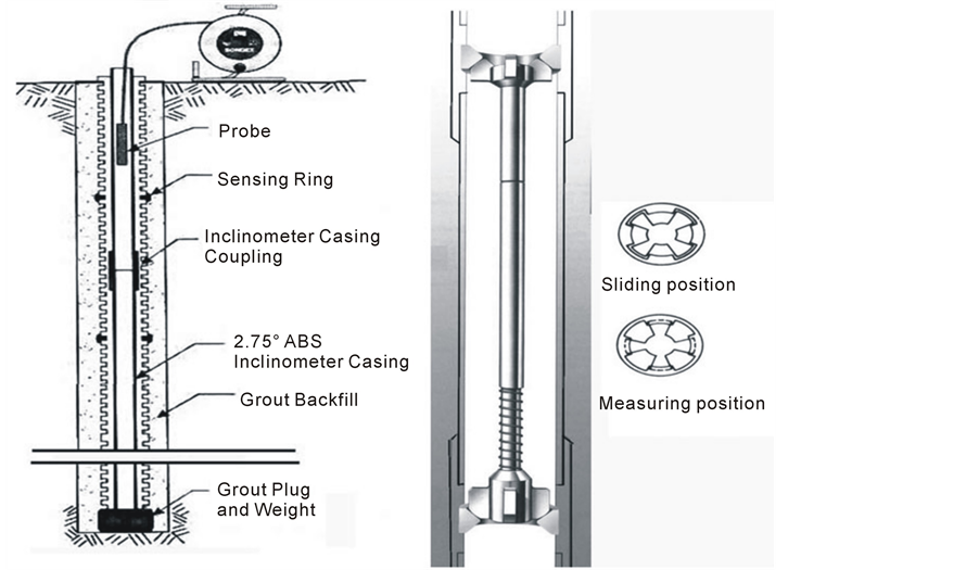
Figure 7. Magnetic extensometer and fixed re-installable micrometer (FIM) of the sliding micrometer.
and pressures necessary to have a stable tunnel face. Pore pressures are taken into account, but generally only a hydrostatic pressure distribution is assumed. However, the construction of a tunnel uses liquids pressurized with pressures different from the hydrostatic pressure: betonies slurry at the tunnel face and grout mortar at the tail void. This will lead to excess pore pressures. Knowledge of these excess pore pressures appears to be of importance for the stability of the tunnel face and the final pressures on the lining. Piezometer is the simplest form of Piezometric measurement is the monitoring of water levels in cased boreholes (internal diameter of casing 20 to 60 mm) [16] .
The plot below shows the results from a typical test in the height of the water level in the rising tube (piezometer) is measured with an electric water level gauge. The device is mounted on the end of the casing and the gauge body lowered into the tube. Once the electrode integrated in the plumb touches the surface of the water, an electric circuit is closed and a pilot lamp comes on. The depth is read off the scale on the cable. The height of the tube end is determined in advance by a levelling measurement. Pour water pressure measurement was carried out by various types of piezometers [17] :
Casagrande Piezometer: A simple open standpipe placed in a borehole, it consists of a PVC standpipe with a permeable membrane tip (Figure 9).
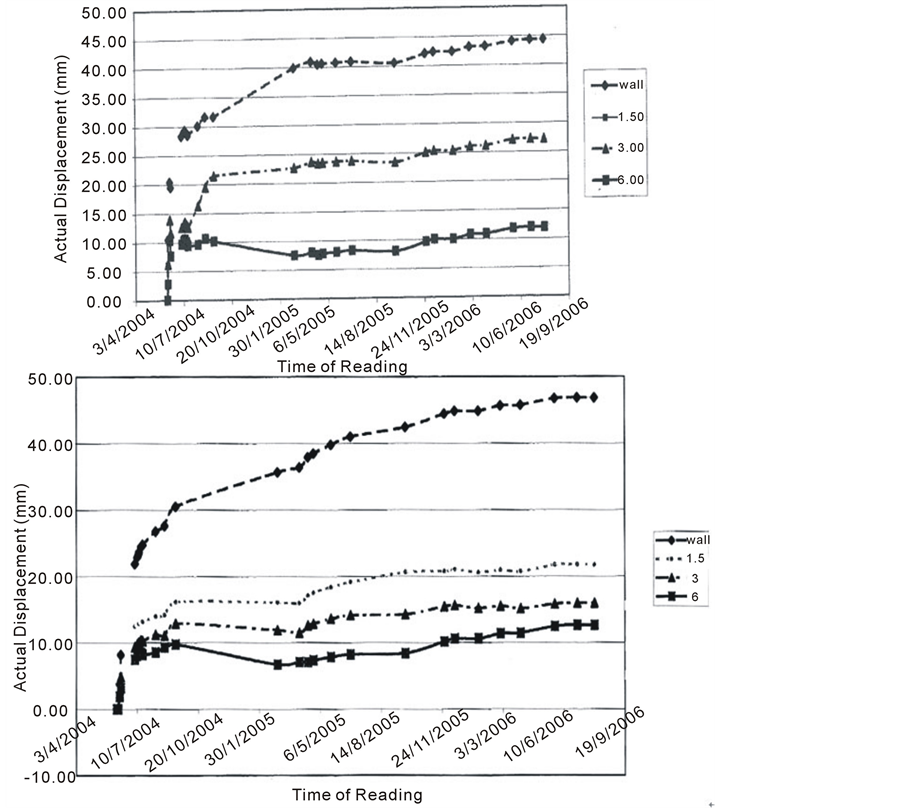
Figure 8. The actual displacement curve of the right rock mass and left rock mass in station 10 of Taloun pilot tunnel.
Pneumatic Piezometer: Dry nitrogen is introduced down an inlet tube which is blocked with a flexible diaphragm (Figure 9).
The first series and the second series of tests were run for 280 days (Figure 10).
7. Geophysical Testing Methods
Geophysical tests are indirect methods of exploration in which changes in certain physical characteristics such as magnetism, density, electrical resistivity, elasticity, or a combination of these are used as an aid in developing subsurface information. Geophysical methods provide an expeditious and economical means of supplementing information obtained by direct exploratory methods, such as borings, test pits and in situ testing; identifying local anomalies that might not be identified by other methods of exploration; and defining strata boundaries between widely spaced borings for more realistic prediction of subsurface profiles. The important various tests include [18] :
Seismic refraction tomography (SRT) which is important to investigate the loosing rock zone of tunnel surface for anchoring design of the some deformed rock mass. Conventional refraction inversion methods use a layered model approach. The subsurface is divided into a number of continuous constant velocity layers having velocities and thicknesses which are modified through interactive forward modeling in an effort to match travel times determined from the field data. These conventional methods require sections of travel time curves to be
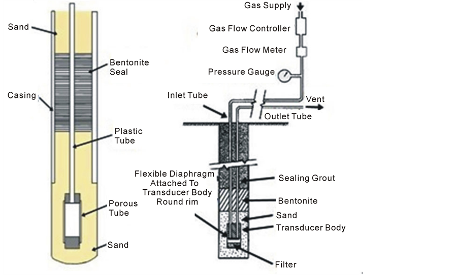
Figure 9. Casagrande Piezometer and Pneumatic Piezometer.

Figure 10. Casagrande piezometer and pneumatic piezometer.
mapped to refractors, a task that can be difficult in several geological situations. Detectors (geophones) are positioned on the ground surface at increasing distance from a seis mic impulse source, also at the ground surface. The time required for the seismic impulse to reach each geophone is recorded a seismic device like that shown in figure 11 shows contour lines that represented boundaries between compression wave velocity gradients [18] .
The cross-hole seismic technique was used to identify the extent of the Excavation Damage Zone (EDZ) is in a test tunnel and in a tunnel under construction. At least 2 boreholes are required: a source borehole within which a seismic pulse is generated, and a receiver borehole in which a geophone records generated compression and shear waves (figure 12). For increased accuracy additional receiver boreholes are used. Receivers must be properly oriented and securely in contact with the side of the borehole [19] . Boreholes deeper than about 30 ft should be surveyed using an inclinometer or other device to determine the travel distance between holes [20] , [21] .
8. Conclusion
Based on mentioned topic, laboratory testing is a fundamental element of a geotechnical investigation. The ulti-
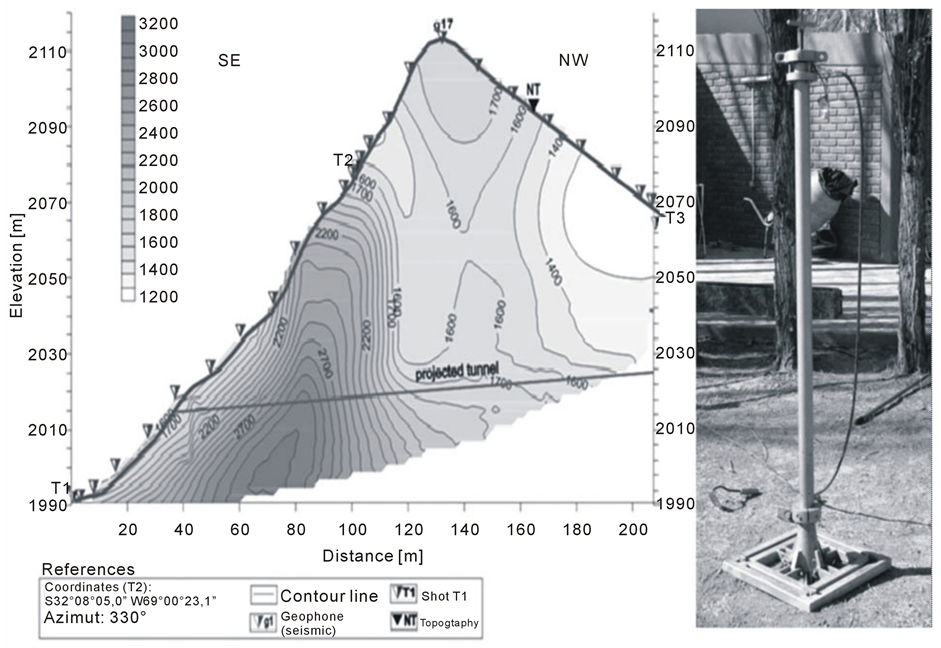
Figure 11. TAMPER seismic wave generation system and seismic refraction tomography profile.
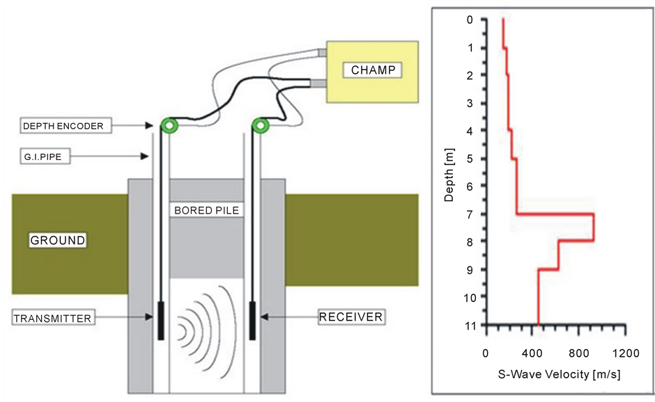
Figure 12. Cross-Hole devices and Resulting S-wave velocity profile.
mate purpose of laboratory testing is to utilize repeatable procedures to refine the visual observations and field testing conducted as part of the subsurface field exploration program, and to determine how the soil or rock will behave under the imposed conditions. Laboratory testing of soil and rock samples to characterize materials; determine engineering properties for use in design; testing in accordance with specified standards; high-pressure 3-axial testing, large diameter 3-axial tests, dynamic testing with high-response, electro-hydraulic, closed loop MTS equipment, and high temperature testing; slake durability testing. Detailed soil laboratory testing is required to obtain accurate information including classification, characteristics, stiffness, strength, etc. for design and modeling purposes. Testing are performed on selected representative samples (disturbed and undisturbed) in accordance with ASTM standards. Rock Testing is generally controlled by the discontinuities within the rock mass and not the properties of the intact material. Standard rock testing evaluate physical properties of the rock included density and mineralogy in thin-section analysis. The mechanical properties of the intact rock core included uniaxial compressive strength, tensile strength, static and dynamic elastic constants, hardness of indices.