1. Introduction
The world prices for the energy resources have been rising up till now, which was caused by the world market trends and by other factors. The Ukrainian situation is complicated by the fact that major part of the most important energy carriers (natural gas and oil) need to be purchased abroad (from Russia and other countries). Such a state of things is putting forth a very important task—the task of energy carrier saving.
Efficient consumption and saving of energy is possible only if metering is carried out with high accuracy and on every step and branch of supply of energy carriers. The accuracy of such a metering is defined by technical base, normative base, metrological base and the professional level of personnel.
The present situation on the US gas market (when there is surplus of gas and its price is low) does not diminish the importance of accurate metering of fluid energy carriers (natural gas in particular) especially for countries in other parts of the world.
2. Normative Base for Flow Rate Measurement
In order to control consumption of fluid energy carriers (natural gas, hot water, overheated steam etc.) the differential pressure method is applied. This method is used for measurement of energy carrier flow rate and volume in pipes with internal diameter of 50 mm and more.
Metering of fluid energy carriers by means of differential pressure devices in Europe is carried out according to the requirements of ISO 5167.1,2,3,4-2003 [1] -[4] . In CIS countries the new Intergovernmental Standard GOST 8.586.1,2,3,4,5-2005 [5] -[9] is in force. The first four parts of this Intergovernmental Standard were developed as modified versions of ISO 5167.1,2,3,4-2003 and the fifth part of GOST 8.586.5-2005 covers the requirements of CIS laws on measurement of energy carrier flow rate and volume and normalizes the procedure for measurements.
The Intergovernmental Standard GOST 8.586.1,2,3,4,5-2005 was developed by authors of this paper together with scientists and specialists from “Ukrmetrteststandard” National Standardization Body (Ukraine) and with experts from “Gazmetrologia” Field Metrology Centre of “Gazprom” Joint-Stock Company (Russia). This Standard was implemented in Russia in 2007 as a national Standard. And in 2010 this Standard was implemented in Ukraine as DSTU GOST 8.586.1,2,3,4,5-2009.
The most important thing here is that based on the analysis we carried out we can say that implementation of the new Standard will provide improvement of accuracy of energy carrier metering.
It should be mentioned that the new Standards in force (ISO 5167.1,2,3,4-2003 and GOST 8.586.1,2,3,4,5- 2005) differ from previous Standards considerably. The most significant distinctions are new limitations for application of the differential pressure method, new mathematical formulae for main coefficients of flow rate equation, new requirements to pipe straight lengths and fittings, new requirements to application of flow straighteners and flow conditioners and finally new methodology for assessment of uncertainty of results of flow rate and volume measurement. The detailed comparative analysis of various normative documents as well as the principle of the differential pressure method is presented in [10] .
An important distinction between GOST 8.586.1,2,3,4,5-2005 and ISO 5167.1,2,3,4-2003 is that the first one covers a wider area of application of the differential pressure method. In particular there is a possibility to take into account the roughness of pipe internal surface by introducing the corresponding correction coefficient into the flow rate equation. In a similar way there is a possibility to take into account other influencing factors. Additionally there is normalization of fluid volume measurement in differential pressure flow meters as well as normalization of uncertainties of fluid flow rate and volume measurement in GOST 8.586.1,2,3,4,5-2005.
Naturally such significant distinctions between the new Standards and the previous ones cause considerable difficulties during implementation of the first. In particular, for every flow meter at least the following tasks have to be accomplished:
• verification of conditions (constraints) for application of the differential pressure method according to the requirements of the new Standards;
• verification of pipe straight lengths according to the requirements of the new Standards;
• calculation of parameters of primary device, pipe straight lengths and flow meter in general according to the requirements of the new Standards;
• calculation of uncertainty of results of fluid flow rate and volume measurement according to the requirements of the new Standards.
When accomplishing these tasks it is very important to carry out the design of a flow meter (and of a whole metering system) optimal as to the accuracy of measurement i.e. flow meter providing minimum uncertainty of fluid flow rate and volume measurement.
The methodology of the mentioned above verifications, calculations and design of differential pressure flow meters was not formalized even for previous Standards. Such methodology is developed by us according to the requirements of the new Standards.
In order to simplify accomplishment of the mentioned above tasks and implementation of new Standards (GOST 8.586.1,2,3,4,5-2005) we propose to accomplish the developed methodology of calculations and design of flow meters by means of a specialized computer program: system for computer aided calculation and design of differential pressure flow meters.
Such a system with the name “Raskhod-RU” CAD [11] was developed in Institute of Energy Audit and Energy Carrier Accounting. By means of this computer program all the mentioned above tasks of verifications, calculations and design of flow meters can be accomplished. “Raskhod-RU” CAD meets the requirements of new Standards and this computer program is certified in Ukraine and in Russia.
3. Description of “Raskhod-RU” CAD System
“Raskhod-RU” CAD is intended for design of flow meters for 48 fluids including the following: natural gas, humid oil gas, overheated steam, dry saturated steam, water, air, nitrogen, argon, oxygen etc. All valid procedures for calculation of compressibility factor for natural gas (NX19 mod.; GERG-91 mod.; AGA8-92DC mod.; VNIC SMV; SD 7-2005) are implemented in the program.
At present “Raskhod-RU” CAD is available in Ukrainian, Russian, Kazakh and English.
The following four different types of calculation of flow meter parameters can be accomplished by means of “Raskhod-RU” CAD:
• calculation of flow meter parameters for the given upper limit of differential pressure measurement;
• calculation of flow meter parameters for the given allowable pressure loss at the primary device;
• calculation of flow meter parameters to secure minimum uncertainty of flow rate measurement;
• calculation of flow meter parameters for the given specifications of primary device and pipe (the so called inverse calculation of flow meter).
The first three types of calculation are applied at initial design of a differential pressure flow meter. In the second and the third types of calculation an optimization problem is solved to minimize pressure losses at the primary device or to minimize the uncertainty of flow rate measurement respectively. And the fourth type of calculation is applied to define the parameters of an existing flow meter and the conditions of its application according to the requirements of new Standards (GOST 8.586.1,2,3,4,5-2005).
When designing a flow meter “Raskhod-RU” CAD gives the possibility to choose one of the three possible configurations (schemes) of the flow meter:
• with separate measurement of flow parameters;
• with flow rate and volume calculator;
• with measuring complex.
Here the program provides a possibility to specify the parameters of up to four measuring transducers (installed in series) in each channel of measurement of a flow parameter (fluid pressure or temperature or differential pressure across the primary device). In order to provide a wider range of flow rate measurement there is a possibility to specify the parameters of additional measuring transducers (installed in parallel) in the channels of differential pressure measurement and fluid pressure measurement. Example of application of two differential pressure transducers in a flow meter to widen the range of flow rate measurement with an uncertainty of no more than 3% is given on Figure 1.
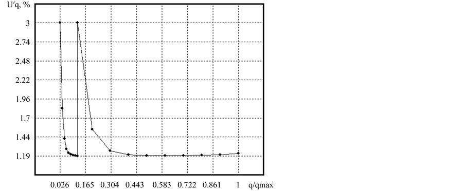
Figure 1. Curve of relative expanded uncertainty of fluid flow rate measurement versus relative flow rate.
After choosing the type of the problem to be solved (type of calculation) the following input data should be entered:
• parameters and characteristics of the fluid;
• parameters and characteristics of the primary device;
• parameters and characteristics of the pipe;
• parameters and characteristics of the pipe straight lengths and fittings;
• parameters and characteristics of the measuring and calculating instruments;
• parameters and characteristics of the flow meter.
The part of the program for entering the parameters and characteristics of the fluid consists of the fields where the input data should be entered (the list of the input parameters and characteristics is individual for each type of fluid). The parameters and characteristics for natural gas including the method for calculating the gas compressibility factor (GERG-91 mod.) are shown on Figure 2.
The part of the program for entering the parameters and characteristics of the primary device is shown on Figure 3 (orifice plate with corner pressure tappings in this example). The list of input parameters and characteristics is individual for each type of primary device and pressure tappings. The drawing of the primary device appears in the dialog box after choosing the type of the primary device. All the types of standard primary devices according to GOST 8.586.1,2,3,4,5-2005 and ISO 5167.1,2,3,4-2003 are included in “Raskhod-RU” CAD. The similar dialog boxes are made for other parameters and characteristics of the flow meter.
It should be mentioned that calculation and design of a differential pressure flow meter is a multi-optional problem.
“Raskhod-RU” CAD is an interactive program, which means that each step of the user is being analyzed and in case of a mistake or any wrong input data the warnings, tips or recommendations are returned by “RaskhodRU” CAD. The most important tips are those concerning inconformance to the requirements of new Standards. In this case “Raskhod-RU” CAD is like an educational software for teaching the requirements of new Standards and for teaching the design of a differential pressure flow meter.
The interactive recommendations of “Raskhod-RU” CAD provide the possibility not only to design a differential pressure flow meter according to the requirements of new Standards but to minimize the uncertainty of flow rate measurement. These recommendations should be taken into account by the user and the input data should be corrected according to the recommendations.
At the end of such an iterative process the calculation protocol for a differential pressure flow meter which
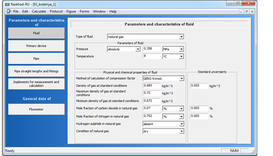
Figure 2. Dialog box for entering the parameters and characteristics of the fluid (natural gas in this example).
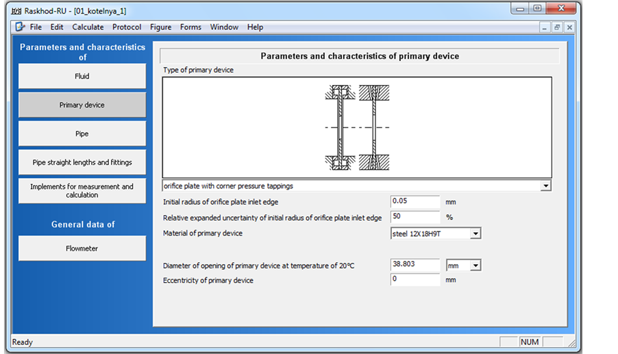
Figure 3. Dialog box for entering the parameters and characteristics of the primary device (orifice plate in this example).
meets the requirements of the new Standards is returned by the program (see Figure 4). We can get such a protocol without iterations if all the input data are correct. In any case the “Raskhod-RU” CAD would not return a calculation protocol for a flow meter which does not meet the requirements of the new Standards.
The following advantages of “Raskhod-RU” CAD should be specified:
• user friendly interface of the program providing quick and easy learning of possibilities of the program and maximum using of these possibilities which is achieved by logical and understandable distribution of input data among the dialogue boxes; the interface of the program is made in such a way that the dialog boxes are being changed during entering the input data (the fields for the unnecessary parameters and characteristics are taken away if needed);
• interactive shell for data input which is especially important for pipe straight lengths, in particular there is a possibility to use flow straighteners and flow conditioners in the pipe as well as various options for mounting the thermometer;
• automatic control of dialogue boxes during entering the input data by the user which provides avoiding unforeseen mistakes;
• possibility to save the input data files and no possibility to save the calculation protocol (in order to eliminate the possibility of distortions in the protocol);
• impossibility to carry out calculation and design and to get a calculation protocol for a flow meter which does not meet the requirements of the new Standards;
• display of warnings about additional uncertainties of measurement results and possible ways to eliminate these uncertainties according to the requirements of new Standards;
• high quality visualization of calculation results which simplifies the analysis and application of the results, in particular there are curves of flow rate measurement uncertainty versus flow rate or other parameters; there are also drawings of primary devices and pipe straight lengths and fittings etc.;
• reliable protection against unauthorized use of the program.
4. Design of Optimal Primary Device
A particularly important advantage of “Raskhod-RU” CAD is the possibility to carry out design of a flow meter optimal as to the accuracy of flow rate measurement. As an example the curve of relative expanded uncertainty
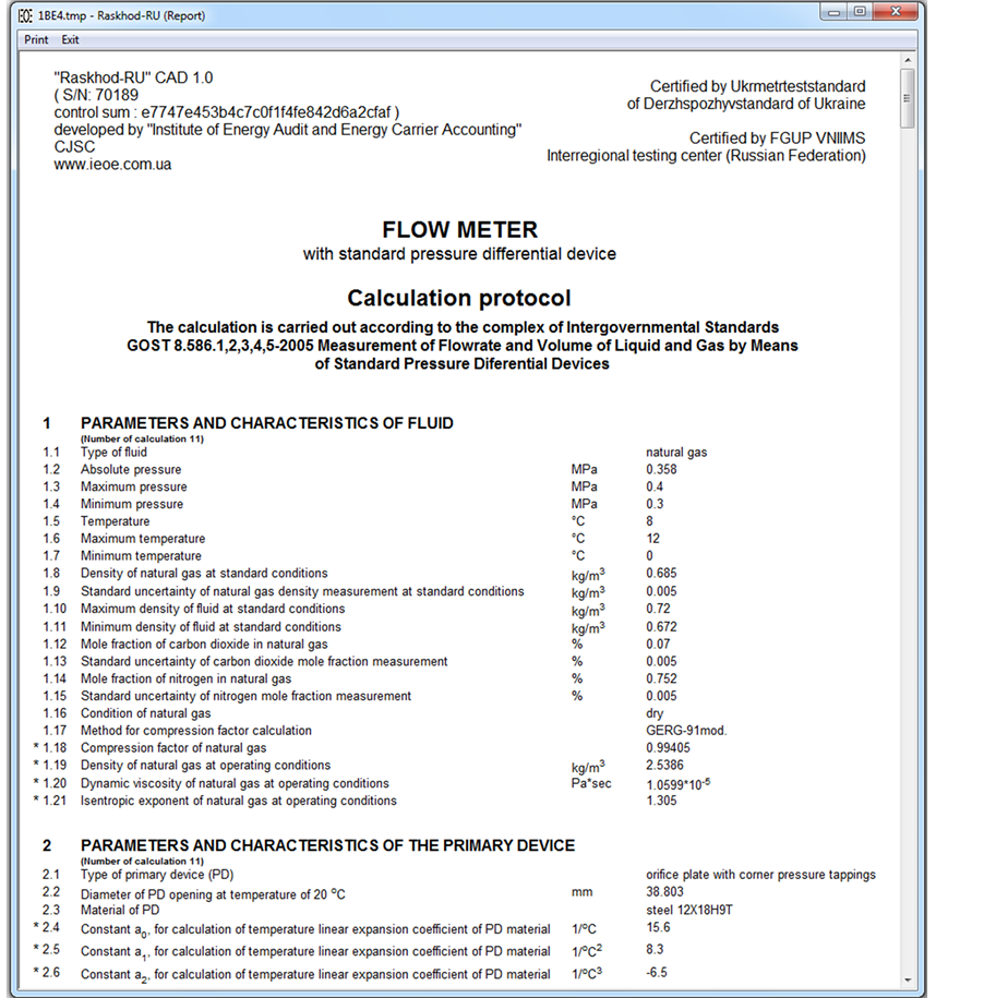
Figure 4. The flow meter calculation protocol (part of the protocol).
of fluid flow rate measurement versus diameter ratio of primary device is shown on Figure 5. There is a table under the curve with these values together with upper limits of differential pressure measurement and with diameter of the primary device opening. The presented curve and table demonstrate the possibility of obtaining maximum accuracy of flow rate measurement when designing a differential pressure flow meter. In the given example the highest accuracy is obtained for the flow meter number three.
No matter what type of calculation is chosen by the user the calculation results are returned in the following way. After all the input data were entered the “Calculate” should be selected in the top menu of the program (see Figure 2 and Figure 3). The main calculation results will be displayed in the same dialog box. After selecting “Protocol” in the top menu of the program the calculation protocol with all the input parameters and characteristics together with calculation results and with drawings will be displayed in a separate window (see Figure 4). After selecting “Figure” in the top menu of the program the curve of relative expanded uncertainty of fluid flow rate measurement versus flow rate (or versus diameter ratio of the primary device in case of making the design of a flow meter optimal as to the accuracy of flow rate measurement) will be displayed in the same dialog box. The calculation results can be printed out.
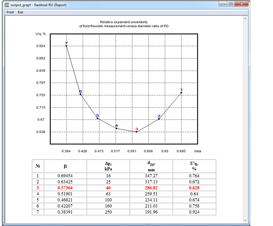
Figure 5. Curve of relative expanded uncertainty of fluid flow rate measurement versus diameter ratio of the primary device together with the table of the corresponding values (calculated by the program).
5. Verification and Design of Pipe Straight Lengths
In order to carry out verification of pipe straight lengths for an existing flow meter by means of “Raskhod-RU” CAD the fourth type of calculation should be selected (calculation of flow meter parameters for the given specifications of primary device and pipe) and all the input data should be entered. After clicking on “Calculate” in the top menu the program will make verification of all the pipe straight lengths. If they meet the requirements of Standards [5] -[9] with “zero additional uncertainty” in the discharge coefficient, then the main calculation results are returned and no warnings are displayed. If the pipe straight lengths meet the requirements of the Standards with “0.5% additional uncertainty” in the discharge coefficient, the corresponding warning with recommendations is displayed and the main calculation results are returned. Here the program provides recommendations with a few options on how to modify the existing configuration of the pipe straight lengths in order to eliminate the “0.5% additional uncertainty” in the discharge coefficient.
If any pipe section of the existing flow meter is too short and the pipe straight lengths do not meet the requirements of the Standards, no calculations are made after clicking on “Calculate”. A dialog box appears with a corresponding warning and description of the pipe section which does not meet the requirements of the Standards. Here in the dialog box the recommendations with a few options are given on how to bring the pipe straight lengths of the flow meter in conformance to the Standards.
To design the pipe straight lengths for a new differential pressure flow meter by means of “Raskhod-RU” CAD again the fourth type of calculation should be selected and all the input data should be entered. But in the part of program for entering the “Pipe straight lengths and fittings” the types of fittings should be specified and the pipe straight lengths should be entered as equal to zero. After clicking on “Calculate” the program will return the minimum pipe straight lengths according to the requirements of new Standards with “zero additional uncertainty” in the discharge coefficient.
The example of verification of pipe straight lengths for an acting natural gas metering system is presented further in this paper. The pipeline configuration of the flow meter is shown on Figure 6 (the pipe straight lengths are given in millimeters). The results of verification are presented in Table 1.
The following denotations are made in Table 1: PD is the primary device (orifice plate in this example); TT is temperature transducer; Fit.1 is the first fitting upstream of PD; Fit.2 is the second fitting upstream of PD; Fit.3 is the third fitting upstream of PD; L1 is the distance between Fit.1 and PD; L2 is the distance between PD and the first fitting downstream of PD; L3 is the distance between Fit.1 and Fit.2; L4 is the distance between Fit.2 and Fit.3; L/D is distance in pipe diameters; U’L is the additional uncertainty in the discharge coefficient caused by reduction of the pipe straight length; U’Lt is the additional uncertainty in the discharge coefficient caused by reduction of the distance between TT and PD.
The minimum A pipe straight length in Table 1 is the minimum pipe straight length with “zero additional uncertainty” in the discharge coefficient and the minimum B is the minimum pipe straight length with “0.5% additional uncertainty” in the discharge coefficient.
As we can see from Table 1 the distance between fitting 1 and fitting 2 does not meet the requirements of
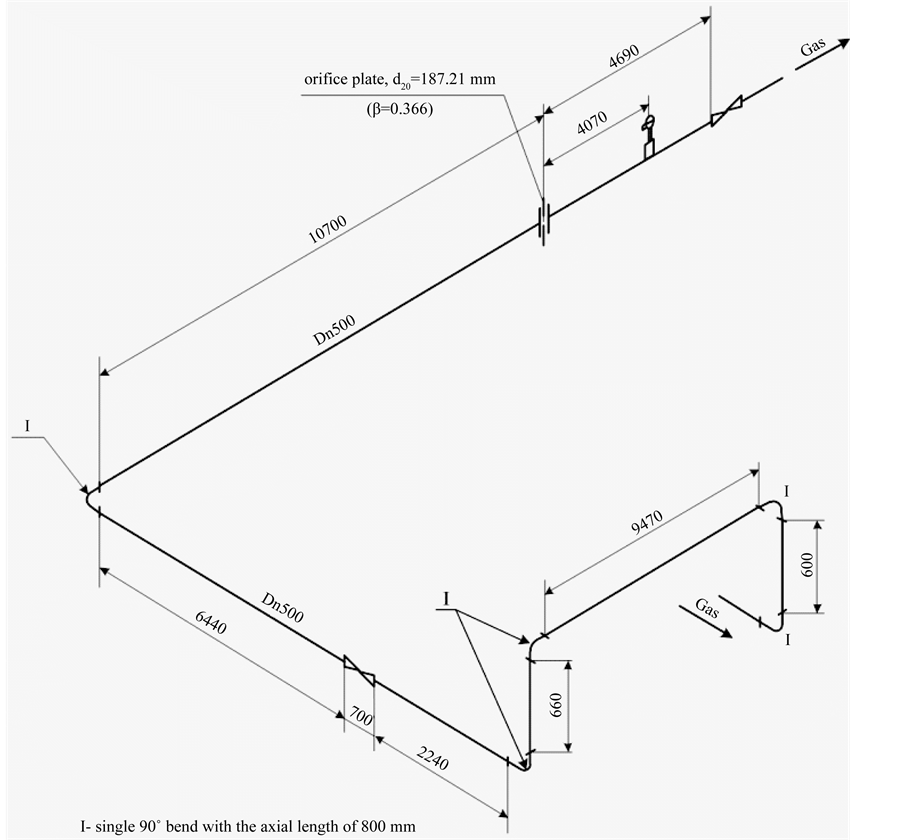
Figure 6. Axonometric diagram of pipe configuration of an acting natural gas flow meter.

Table 1. Verification of pipe straight lengths for the natural gas flow meter.
Comment 1. The minimum B pipe straight length is defined without taking into account the location of the temperature transducer. Comment 2. If the distance between Fit.2 and Fit.3 is less than 5D and the required pipe straight length for Fit.3 is bigger than that for Fit.2, then the distance between Fit.1 and Fit.2 is defined according to the type of Fit.3 (see p.6.2.8.а.2 of GOST 8.586.2-2005 [6] ). Comment 3. The “Indefinite type of fitting” is derived as a consequence of uniting the two “two 90˚ bends in perpendicular planes” with the distance between them smaller than 30D (see requirement in p.А.1.4 of Annex А of GOST 8.586.2-2005 [6] ).
GOST 8.586.2-2005 [6] . It should be taken into account that fitting 3 (“indefinite type of fitting”) includes the type of fitting “two 90˚ bends in perpendicular planes (l < 5D)”. There is a requirement in GOST 8.586.2-2005 Standard [6] to control the distance between a fitting consisting of bends combination and the primary device irrespectively of the number of fittings between the primary device and the bends combination (p.6.2.8.b of GOST 8.586.2-2005 [6] ). The same requirement is present in ISO 5167-2:2003, p.6.2.8.b [2] . For the flow meter under consideration the distance between the fitting “two 90˚ bends in perpendicular planes (l < 5D)” and the primary device should be not less than 24.037 m. And here in the existing flow meter this distance is actually equal to 20.88 m (with taking into account the lengths of fittings). That is why reconstruction of the pipeline of the metering system is required.
Due to the complicated configuration of the pipeline it is recommended to install the “Zanker” flow conditioner plate. This would provide the possibility to bring the existing system in conformance to GOST 8.586.2- 2005 Standard [6] without increasing the pipe straight lengths. And this is also the least expensive option. For the given gas metering system the “Zanker” flow conditioner plate can be installed upstream of the primary device at the distance of 3.84...6.35 m.
All the minimum A and minimum B pipe straight lengths in Table 1 as well as distance between the “Zanker” flow conditioner plate and the primary device in our recommendations are defined using “Raskhod-RU” CAD and by applying the methodology described above.
It should be mentioned that one of distinctions between GOST 8.586.1...5-2005 and ISO 5167-1...4:2003 is that an “indefinite type of fitting” is introduced in GOST 8.586.1...5-2005. This type of fitting defines any other fitting than those mentioned in Table 3 of ISO 5167-2:2003 [2] and Table 4 of GOST 8.586.2-2005 [6] . At some cases the “indefinite type of fitting” can be derived as a consequence of uniting two fittings. The pipe straight length between the “indefinite type of fitting” and the primary device is the biggest compared to all the other types of fittings.
Verification and design of pipe straight lengths as well as design of optimal primary device are very important parts of technical examination and audit of the differential pressure flow meters. The technique for auditing the differential pressure flow meters was developed by us and the description of the technique is given in [12] .
6. Conclusion
The methodology for calculation and design of differential pressure flow meters is developed by us according to the requirements of the new Standards (GOST 8.586.1,2,3,4,5-2005). This methodology is implemented in “Raskhod-RU” CAD which enables computer aided calculation and design of differential pressure flow meters. At the same time, verification of conditions (constraints) for application of the differential pressure method according to the requirements of the new Standards can be carried out by this computer program which simplifies the process of implementation and application of the new Standards significantly. Application of optimal flow meters as to the accuracy of flow rate measurement, designed by means of “Raskhod-RU” CAD, will provide improvement of accuracy of fluid energy carrier metering.