1. Introduction
The improvements in high-speed optical components and electronics support new optical communication systems with high data rates. Optical components can be shared between different WDM channels. WDM can increase bandwidth over optical fiber by sending several signals concurrently at different wavelengths [1]. Therefore, it can increase the system capacity while reducing the cost of the system. The possible bit rate for each WDM channel has been increased to more than 40 Gb/s and this implementation gets a high possibility for dispersion [2].
Optical OFDM (O-OFDM) is one of the advanced and efficient modulation techniques that have been used in the modern optical communication systems. O-OFDM is used as the modulation technique in advanced optical communication systems because it offers robustness to narrowband interference and frequency selective fading [3]. It is being offered as the premier long-haul transmission design in direct detection and coherent detection. The integration of DDO-OFDM with WDM will provide a small increase in the nonlinearity of the optical system even with high number of channels. In addition, the main goal of DDO-OFDM is to have a simple transmitter and receiver which will provide a low cost system when compared to other methods such as Coherent Optical OFDM (CO-OFDM) [3,4].
O-OFDM is a part of multicarrier modulation (MCM) where the data information is transmitted over many subcarriers of lower rate. [4].
O-OFDM modulation technique provides a number of great advantages when it is used in the optical communication system. It can reduce the amount of dispersion produced by multipath delay spread. Moreover, all OOFDM symbols used a guard interval, which gives the advantage of eliminating Inter-Symbol Interference (ISI) produced by a dispersive channel [5]. Furthermore, the O-OFDM symbol is regularly extended to avoid InterCarrier Interference (ICI) [6]. In addition, using OOFDM in long-haul systems can compensate the linear distortions in the optical fiber, such as group velocity dispersion (GVD).
O-OFDM uses different subcarriers to send low rates in parallel data streams. The M-array Quadrature Amplitude Modulation (QAM) or Phase Shift Keying (PSK) is used to modulate the subcarriers before being transported on a high frequency microwave carrier.
Because the duration of symbol is extremely longer than the root-mean-square (RMS) delay of the optical wireless channel, the multicarrier modulation has strong robustness to ISI. Consequently, O-OFDM multilevel quadrature amplitude modulation (MQAM) encourages the delivering of very high data rates [6-8]. In the optical communication system, the information is transmitted on the optical signal intensity and hence it can be only positive (unipolar). In this paper, direct detection is used instead of coherent detection which means that there is no laser at the receiver acting as a local oscillator.
2. System Design
The paper studies the combination between DDO-OFDM and DWDM to get high data rates (1,050 Tb/s). Figure 1 presents the theoretical design of the system-the design is composed of three major parts: DDO-OFDM transmitter, a fiber optic transmission link, and the DDO-OFDM receiver. The use of WDM is to support a system of high data rates with thirty channels, each with 35 Gb/s and 100 GHz of spacing, to achieve data rates of 1.050 Tb/s.
2.1. DDO-OFDM Transmitter
A pseudo-random binary sequence (PRBS) block creates a random bit sequence to be the information of the OFDM signal. Then it is connected to a Marry-QAM sequence generator. In this design, 64-QAM is used and followed by the OFDM modulator [9]. Consequently, the RF-IQ mixer is used to transform the OFDM signal to a radio frequency (RF) [9-11]. The O-OFDM parameter is shown in Table 1. After that, the signal is mixed with the light wave generated from the continuous wave (CW) laser by an external modulator, which is a Mach-Zehnder modulator (MZM) [12-14]. Figure 2 shows the design of OFDM transmitter. The signal that is produced from the MZM is connected to a fiber optic transmission link.
Table 1 shows the OFDM transmission parameters consisting of 512 sub-carriers, and a large Fast Fourier Transform (FFT) of 1024 with a bandwidth of 20MHz. The size of the cyclic prefix (CP) is calculated by multiplying CP with the whole number of electrical subcarriers (NFFT).
The output of O-OFDM is modulated by a Quadrature modulator corresponding to Equation (1) [15,16].
 (1)
(1)
where I and Q are the input electrical signals, G presents Gain, fc = 7.5 GHz is the carrier frequency, b stands for bias, and c is the phase of the carrier.
2.2. Long-Haul Optical Fiber Link
Thirty O-OFDM signals are multiplexed by using WDM and then sent to the optical fiber link. In this design, a
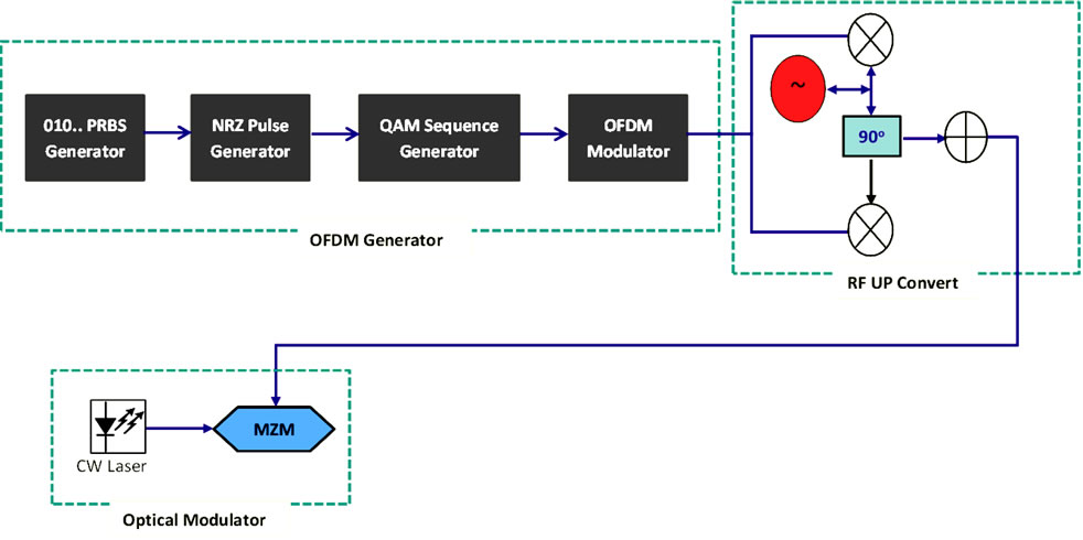
Figure 2. DDO-OFDM transmitter block diagram.
single-mode fiber (SMF) with a wavelength around 1550 nm is used because it offers low attenuation at 0.2 dB. The total bandwidth provided at 1550 nm is approximately 8 THz. The total available bandwidth is divided into various channels, usually with 100 or 50 GHz bandwidth, and is known as dense wavelength-division multiplexing (DWDM). A multi-span of optical fiber consisting of 30-span of 120 Km SMF is used. Also, two erbium doped fiber amplifiers (EDFAs) are used before and after the optical fiber to compensate for the loss in the fiber. After linking the optical fiber transmission, the signal is connected to a WDM demultiplexer to separate the thirty OFDM signals.
2.3. DDO-OFDM Receiver
As shown in Figure 3, the output signal is received from the optical fiber by a PIN photodetector to convert the optical signal to an electrical signal. After that, the OFDM signal is recovered from the RF to a baseband by a Quadrature demodulator and then the signal is transmitted to the O-OFDM demodulator. Finally, a QAM sequence decoder is used to decode the signal and to generate a binary signal. Table 2 shows the O-OFDM demodulator parameter.
The system design is studied and implemented by using a sufficient simulation program called OptiSystem V.11. The global parameter of the system design is shown in Table 3.
3. Dispersion Compensation Fiber (DCF) Design
One of the significant parameters that affect the quality of the signal over long haul transmission link is the dispersion in the fiber. DCF is a highly efficient technique to compensate the chromatic dispersion (CD) in highspeed transmission systems. DCF is designed to achieve a high negative dispersion of up to −80 ps/nm, which can adjust the amount of CD in the optical fiber. The dispersion is broadband, so it has the advantage of adjusting multiple WDM channels at the same time without phase distortion [17].
In this paper, the dispersion postcompensation technique is used to compensate the dispersion and support the system to transmit over 3600 km SMF as shown in Figure 4.
4. Results and Discussion
After simulating the design by using Optisytem, many parameters are considered to measure the system performance.
The constellation shows a two-dimensional scatter diagram of the signal. Figure 5 demonstrates a signal modulated 64-QAM. As can be seen from the graph, all sam-

Table 1. OFDM modulator parameters.

Table 2. OFDM demodulator parameters.

Table 3. Simulation global parameters.
ples are free of interferences and noise.
Figure 6 shows the spectrum of 30 channels of 35 Gb/s each after WDM, with 100 GHz channel spacing. The modulation parameter of each channel has the same settings. The carrier frequencies of the thirty optical signals starting from 193.1 to 196 THz with a spacing of 0.1 THz and each with an average power of 5 mW and linewidth of 1 MHz.