A Wavelet Transform Method to Detect P and S-Phases in Three Component Seismic Data ()
1. Introduction
Seismic events such as earthquakes cause a release of energy represented by seismic waves that can be recorded by seismic monitoring stations. Detection of seismic waves and estimation of their arrival times provides information about earthquake location and magnitude. Analysis and detection of seismic waves may be done by visual inspection by a trained analyst or automatic analysis software.
Rapid and accurate detection of seismic waves is of great importance in locating earthquakes [1-10]. Automatic detection techniques are of interest because they can be processed in near real-time; they apply a consistent set of metrics and are repeatable. However, it is often very difficult to determine consistent estimates of P and S waves if they have low signal-to-noise characteristics, particularly if arriving at seismic stations at regional distances.
The objectives of this research are:
1) To design an algorithm for the detection and analysis of the two main types of seismic body waves (P and S-phases).
2) To test the algorithm using seismic events recorded by various stations at local and regional distances, and then compares the results with the results obtained by other methods.
Several methods have been tried recently these that have involved digital signal processing in both time and frequency domains [11-13]. The method adopted here is wavelet transform using an approach initially developed by K. Anant and F. Dowla [11].
The algorithms have been developed in Matlab 6.5TM (http://www.mathworks.com) including signal processing and WaveLabTM (http://www-stat.stanford.edu/~wavelab) toolboxes. WaveLab is a library of Matlab routines for wavelet analysis, wavelet-packet analysis, cosine-packet analysis and matching practice. The algorithms can be run on a laptop with 256 MB RAM or on a mainframe computer.
Seismic Data Used in Testing
Seismic data from Earthquake Monitoring Center in Oman has been used for testing the algorithms. The ANZA Broadband Seismic Network (http://eqinfo.ucsd.edu) also provided analyst reviewed data and STA/LTA automatic detected data used for comparison with the wavelet detector.
The paper structured as follows: An introduction about wavelet transform is given in Section 2. Section 2 also includes description of the discrete time wavelet transforms, its application on seismic signals to match specific features and how the selection of wavelet type has been done in this study. The multiresolution analysis technique and the perfect reconstruction filter banks are explained too. The developed software and methodology are explained in Section 3. The flow charts of the algorithms are illustrated in Appendix B and a detailed annotation is given in Section 3 too. The results are discussed in Section 4. Comments about the testing results and the comparison results with other methods are presented in Section 5.
2. Wavelet Transform Analysis
2.1. Introduction
The wavelet transform is a very useful tool for analysing noisy and transient signals and has the ability to represent the signal in both its time and frequency domains. It is a very useful tool in the analysis of non-stationary signals such as seismic signals due to its ability to resolve features at various scales [14].
The wavelet theory arises in 1909 when Haar constructs the first orthonormal system of compactly supported functions called the Haar basis [15].
The term wavelet has been coined in the field of seismology in 1940 by Ricker, N. [15]. The wavelet theory has been applied on seismic signals by Grossmann and Morlet in 1984 [11]. In 1988, Daubechies developed an orthonormal, compactly supported wavelet basis that is smoother than Haar basis [14-16]. Application of wavelet transform on seismic signals has been done by Anant and Dowla [11], Oonincx, P. J. [12] as well as by Zhang et al. 2003 [13].
The wavelets form a family. The basic form is called the mother wavelet. All the daughter wavelets are derived from this wavelet according the following equation:
 (2.1)
(2.1)
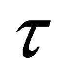
where, s and  are the scale and translation of the daughter wavelet. The term s−1/2 normalizes the energy for different scales, whereas the other terms define the width and translation of the wavelet.
Digital signal analysis using wavelet transforms begins with the construction of a single parent wavelet. The signal is then decomposed into a series of basis functions of finite length consisting of dilated (stretched) and translated (shifted) versions of this parent wavelet function, i.e., wavelets of different scales and positions in time or space. This process is similar to Fourier analysis, where the parent wavelet is analogous to the sine wave, and the basis functions in Fourier decomposition are sine waves of various amplitude, phase, and frequency variations of the parent sine wave [14,17].
Scaling a wavelet simply means stretching (or compressing) it. The smaller the scale factor, the more “compressed” the wavelet. The more stretched the wavelet, the longer the portion of the signal with which it is being compared, and thus the coarser the signal features being measured by the wavelet coefficients. Thus, there is a correspondence between wavelet scales and frequency as revealed by wavelet analysis:
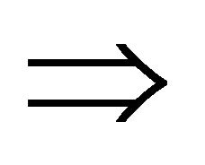
• Low scale s  compressed wavelet
  rapidly changing details
  High frequency ω.
• High scale s  Stretched wavelet
  Slowly changing, coarse features
  Low frequency ω.
The decomposition advantage is very useful in dealing with signals contain features with various frequency characteristics. Another advantage of the wavelet transform is that its analysis can be chosen based on the application [11].
Figure 1 shows seismic signal at top and wavelet coefficients of six scales where “Daubechies 8” wavelet has been used. The smallest scale is the one that contains the highest frequency while the largest scale is the one that contain the lowest frequency.