1. Introduction
With the demanding requirements being placed upon the new fifth generation (5G) mobile communications standard, a totally new radio interface and radio access network has been developed. The 5th generation wireless access technology, which is known as New Radio (NR), could meet the growing needs for mobile connectivity.
The development of the 5G NR or 5G New Radio is the way to enable the 5G mobile network to work and it provides a number of significant advantages when compared to fourth generation (4G).
5G NR has been developed with the aim of taking the requirements and looking at the best technologies and techniques that will be available when 5G starts to be deployed.
5G NR follows Third Generation Partnership Group (3GPP) series of standards similar to Global System for Mobile (GSM), Universal Mobile Telecommunication System (UMTS) and Long Term Evolution (LTE) [1]. 3GPP organization has been developing specifications for 5G NR. In Dec. 2017, First specifications have been published where 5G compliant user equipment (UE) depends on existing LTE for initial access and mobility. So it is called “Non-Standalone (NSA) version”. In June 2018, “standalone (SA)” versions of 5G NR speciation’s have been finalized which works independent of LTE. According to International Telecommunication Union (ITU) [2] [3], there are three different use cases of 5G NR technology: Enhanced Mobile Broadband (eMBB), Massive machine type communications (mMTC) and Ultra Reliable Low Latency Communication (URLLC).
The requirements currently being discussed for 5G are a 1000-times gain in capacity targeting very high data rates of up to 10 Gbps. Fast machine control loops and wireless emergency stop functionality require delays below 1 ms. With the number of sensors increasing, the energy costs and efficiency have to be revolutionized, such that a 10× longer battery life can be obtained and a reduction in the energy cost per bit can be achieved by a factor of 100 to a 1000-fold. To meet massive connectivity demands for IoT, the connectivity density increases to be ten times higher than that of 4G; latency of 5G is also expected to be as low as 1 ms, and the cost to be 100 times lower than cost efficiency of 4G. The global mobile data traffic is expected to reach 69 exabytes per month by 2022 at a compound annual growth rate of 45 percent [4]. These stringent requirements should stand on advanced solutions at entire 5G layers especially physical layer (5G NR). The following solutions are proposed to be conceived in 5G NR.
1) From OMA to NOMA
Over the past few decades, wireless communication systems have witnessed a “revolution” in terms of their multiple access techniques. Specifically, for 1G, 2G, 3G, and 4G wireless communication systems, frequency division multiple access (FDMA), time division multiple access (TDMA), code division multiple access (CDMA), and orthogonal frequency division multiple access (OFDMA) have been used as the corresponding key multiple access technologies, respectively. From the perspective of their design principles, these multiple access schemes belong to the category of orthogonal multiple access (OMA), where the wireless resources are orthogonally allocated to multiple users in the time-, frequency-, code-domain or according in fact based on their combinations. We might collectively refer to these domains as “resources”. In this way the users’ information bearing signals can be readily separated at a low complexity by employing relatively cost-efficient receivers. However, the number of supported users is limited by the number of available orthogonal resources in OMA. Another problem is that, despite the use of orthogonal time-, frequency- or code-domain resources, the channel-induced impairments almost invariably destroy their orthogonality. The basic goal for non-orthogonal multiple access (NOMA) is to support more users than the available resources (time- frequency- code-domains). This increase in users over resources by Non-orthogonal multiple access is adopted by the ultimate cost at receiver complexity due to requirement for separting the non-orthogonal signal. There are several NOMA solutions have been actively investigated, which in general can be divided into, power-domain NOMA, code-domain NOMA and pattern based.
2) Toward Software Defined Radio
A new approach is introduced in mobile communication networks components which is Software-Defined Radio (SDR). The SDR depends on replacing analog hardware components by software programmable tools which rely on Digital Signal Processors (DSPs), general purpose processors (GPPs), and Field Programmable Gate Arrays (FPGAs). SDR based systems are reconfigurable and allow fast-prototyping on a flexible platform. In addition, it reduces developing time and costs in comparison with special purpose processors.
SDR is a platform able to configure different communication standards with different carrier frequencies, variable signal bandwidths, and controlled transmit power. Different communications technologies are such as MIMO and beam forming and multiband.
3) Low Density Parity Check Instead of Turbo Codes
In order to support demands for high throughput in 5G NR, LDPC is introduced to replace turbo codes, prevalent in most modern cellular devices, as the code for forward error correction [5]. LDPC also needs to support incremental-redundancy hybrid Automatic Repeat Request (HARQ), and a wide range of block lengths and coding rates, with stringent performance guarantees and minimal description complexity. Historically, LDPC codes were originally invented and introduced in 1962; despite its early discovery, they were not in use until it was reintroduced by Mackay in 1997. He proved that the Shannon limit can be achieved or even exceeded by LDPC codes similar to turbo codes. LDPC, which considers linear codes, has a sparse parity check matrix consisting low density ones. As a result of the sparsity of the parity check matrix, LDPC codes have relatively simple and practical decoding algorithms. To enhance the decoder gain, Modern LDPC decoders work with soft decision algorithms. After its second discovery and outstanding capabilities to achieve theoretical limits of channel capacity, LDPC codes are currently being used in many communication systems such as 802.16e (Mobile WiMAX), 802.11n (WiFi allowing MIMO) and DVB-S2etc.
In this paper we build an open source SDR-based system to realize the transceiver of the PDSCH according to 3GPP specs. The proposed system provides a prototype for pairing between two 5G users using NOMA technique. In addition, it gives a suitable design for LDPC channel coding. The intermediate stage of segmentation, rate matching and interleaving are also carried out in order to realize a standard NR frame.
The main contributions of this paper are summarized as follows:
a) A prototype for transceiver of the PDSCH of 5G technology according to 3GPP specs: the prototype realizes the elected 5G channel coding for user’s data i.e. LDPC, CRC error correction technique and the pre channel coding stage i.e. segmentation. In addition, interleaving, rate matching and scrambling are implemented as well. Finally NOMA technique including superposition and SIC receiver, and OFDMA modulation is performed in order to realize a complete 5G NR frame.
b) Novel implementation of NOMA technology with 5G compliant instead of LTE compliant: All trials and prototypes for implementing of NOMA are LTE compliant, so this work is first one to deploy NOMA technology in complete 5G platform. We realize superposition coding, reconstitution and SIC of NOMA transceiver in 5G frame format.
c) A labVIEW code word-level of complete physical layer 5G NR modules mentioned above are provided and fully described.
The remainder of this paper is organized as follows. Section 2 presents related work. Section 3 introduces 5G System Architecture and scenarios. Experimental Results and analysis are provided in Section 4. Finally, the paper is concluded in Section 5.
2. Related Work
Efforts to design and implement of 5G technology started from 2012. Many prototypes and testbeds are tried to be deployed for each part of 5G system. DOCOMO [6] has developed a real-time simulator for simulating small-cells, massive MIMO and mmWave. With this simulator, 1000-times increase in the system capacity is achieved. In addition, 90% users achieved 1 Gbps data rate. The world’s first highest data rate of 1.2 Gbps with vehicle running at speed exceeds 100 km/h is performed by Samsung using mmWave at 28 GHz frequency band. The data rate reached to 7.5 Gbps when the vehicle was nearby a stop [7]. A data rate of 10 Gbps in a demonstration has been achieved by Ericsson [8]. The European Commission funded METIS [9] has implemented and developed more than 140 technical components, including: new waveforms, air interface technologies, MAC, multiple access schemes, multi-hop communications, resource allocation schemes, mobility management, and spectrum management technologies.
In the following, we provide a survey for NOMA and LDPC technology concentrating on efforts to implement these technologies in the literature. Then we survey works in using SDR in modern mobile systems. NOMA, which has been recently proposed by 3GPP, considers a promising technology for addressing 5G networks challenges [10] [11] [12]. NOMA has attracted great attention across both academia and industry [13]. Good survey for NOMA in academia side in recent years can be found in [14]. The recent study of NOMA in 3GPP starts in LTE Release-13 under the name Multi-User Superposed Transmission (MUST), mainly focusing on DL transmission. It can be mainly categorized into three categories. Details for NOMA standardization efforts in NOMA can be found in [15].
Many papers suggest a design for NOMA transmitter and receiver. The authors in [16] implement a practical downlink NOMA system based on an open-source SDR platform named as OpenAirInterface (OAI). Their proposed SDR-based NOMA system follows the basic specifications of LTE. While the authors in [17] choose general-purpose-processor-based SDR to implement NOMA system, which is based on an open source LTE program. For the purpose of performance evaluation, and to demonstrate its potential in future 5G mobile networks, over-the-air experiments are carried out on their designed NOMA system. In [18], the authors developed a portable NOMA testbed based on SDR in mini personal computers (PCs). The NOMA testbed has been enhanced from 5 MHz bandwidth to 10 MHz bandwidth. But it is still LTE compliant. In [19], the authors integrate a 5G radio access technology to software radio defined physical layer of IEEE 802.11 p. They superposed two signal using NOMA system and extracted them with successive interference cancellation (SIC).
All these works are built in LTE modules. So it is not consider a complete 5G system. All stages before NOMA such as channel coding, segmentation, interleaving and rate matching are LTE compliant.
On the other hand works related with design or evaluation of LDPC channel coding have deployed LDPC in a standalone based or in LTE physical channels [20] [21] [22]. In [20], the Physical Downlink Shared Channel (PDSCH) encoder and decoder are realized on the OpenAirInterface (OAI) DLSIM platform which provides a complete software implementation of the entire 4G LTE system architecture [7]. In [21] the authors propose an algebra-assisted method for constructing quasi-cyclic-LDPC (QC-LDPC) codes. They apply the proposed algorithm for cases of 5G LDPC codes. The exponent matrices designed at this paper for the smaller base matrix have been accepted by 3GPP for 5G LDPC codes. Due its feasibility and appropriateness of 5G specs of channel coding, it has been chosen to be implemented in our proposed 5G channel coding after programming it using LabVIEW code word-level.
In this paper we implement a prototype for 5G system using SDR as it is the most flexible and inexpensive approach for rapid prototyping of our model. The notion of SDR is to use software as much as possible for implementing communication modules. A typical SDR platform consists of two components [23] : a general purpose programmable platform for signal processing in baseband level and peripheral equipment for frequency conversion and digitalization. By developing an open source software for each communication module, an open source SDR component is generated. An open-source SDR component provides a flexible and cost-effective means for developing SDR applications, where every component of an SDR application can be tailor implemented. Thus, open source signal processing algorithms for 5G system can be easily designed and developed based on open-source SDR.
There are many SDR-based LTE communication modules, OpenAirInterface (OAI), OpenLTE and Amari LTE 100. While OAI & OpenLTE are open SDR-based systems, Amari LTE 100 is closed system. Amari LTE 100 is the most complete SDR based implementation of LTE base station and core network. OAI is fully open-source which provides a complete software implementation of the entire 4G LTE system architecture. All these examples provide design for LTE mobile network, and according to the best of our knowledge there is no open source SDR-based platform for 5G system.
3. 5G System Architecture and Scenario
In this section we introduce a full open source SDR-based prototype platform of 5G new radio system architecture. This platform comprises all communication elements in 5G physical layer. The network architecture of the proposed 5G prototype consists of two UEs and gNB. A downlink full physical layer components of the PDSCH of NR is implemented for the two users and gNB. The physical service data units of the two UEs (transport block) are processed in three separate parts, i.e. channel encoding, scrambling, and finally modulation part. In the channel encoding three processes are carried out in sequence, i.e. CRC algorithms, code block segmentation and finally channel coding with LDPC and interleaving.
The proposed 5G platform is built on two basic components: LabVIEW and NI USRP 2921. LabVIEW is a software for producing, processing and analysis of radio wave channels. The LabVIEW is a system design software provides a graphical user interface and solution for designing methods by combining both textual and graphical mathematical based programming approaches [23]. Different from other conventional programming techniques, LabVIEW has high-level devices to simulate different communication components and produce different waveforms. In addition LabVIEW can connect with a lot of measurements and devices and can store data in reports.
On the other hand NI USRP 2921 is hardware tools that are controlled by LabVIEW through NI USRP hardware driver. It is used to produce signal that is wave formed using LabVIEW in frequency range from 0 to 2.5 GHz and 4.9 GHz to 5 GHz with a bandwidth of up to 20 MHz. The USRP is a high-speed field programmable gateway Array (FPGA) board with a Gigabit Ethernet connection. NI USRP 2921 which is used in this platform has a dual band vertical Antenna.
3.1. Cyclic Redundancy Check
CRC is the first module processes the transport block in 5G NR. CRC block diagram basically adds extra bits (L) that is essential for detecting errors whether in transport block or in Code block. For transport block, gCRC24A (1) with L = 24 is used, while in Code block, gCRC24B is used as will be explained in segmentation stage.
(1)
Cyclic Redundancy Check Encoder: First of all, data must be appended by 24 extra bits. The process depends mainly on XOR-ing the data with a constant divisor value and the remainder is to be added to the data as CRC bits. The generating-zero-for-loop is responsible for adding those bits by getting the size of input data and concatenates or pads them with extra 24 zeros by the “insert into array” block. The feedback node stores each zero generated till the end of the iteration to get an array of zeros of size 24 bits as shown in Figure 1.
Secondly, in order to perform the CRC calculation in the first XOR, the most significant bit (MSB) must be tested first. The MSB is extracted from the concatenated array using the “index array” block. This bit is then tested by AND-ing it with one. The result of the AND-ing is then inserted as a case selector to determine which case to be executed. After that, the MSB is removed by using the “array subset” that takes the size of the concatenated array and subtracts one to get the array without the MSB. The same step is done for the divisor as well.
Thirdly, performing the XOR calculation is done by using a case that is mentioned before. This case depends on the value of the MSB of the data. If the first bit is one, then the case will XOR the first 24 bits of the data with the divisor. While, if the first bit is zero, then the case will XOR the divisor with the padded 24 zeros. The first 24 bits are extracted from the data array by using “array subset” block with index zero and length of 24. Fourthly, in order to continue the long division process, repeating the previous three steps is essential. Another iteration is used which is equivalent to the size of the data without the padded bits. The resulted bits generated from the previous XOR step is used as an input to iteration loop. It is stored in a feedback node-as an initial value—which acts
![]()
Figure 1. LabVIEW implementation of cyclic redundancy check encoder of gCRC24A.
as a register for keeping the last value of the CRC that represents the remainder. These bits are XOR-ed with the divisor if the MSB of the remainder is one, or XOR-ed with zeros of it is zero. In each step, a bit is appended from the data to the remainder at the least significant bit. This step is implemented by starting from bit number 24 in the input data and incrementing the position of the bit in each iteration in order to insert all the bits inside the data to the remainder.
Finally, the resulted remainder (CRC) bits are added to the data replacing the padded bits. And the rate is calculated by dividing the size (number of bits) of the data by the total number of bits which is the data and the CRC bits.
Cyclic Redundancy Check Decoder: The decoder CRC is the same as the encoder but with extra blocks that check the CRC value as shown in Figure 2. When the CRC bits generated from the received data are all zeros then there is no error detected in this segment. If there is an error, the receiver discards the data segment. This check is done by OR-ing all of the CRC bits generated by the receiver together. If there is any bit that is not equal to zero in the CRC then; the output will not be zero. The OR output is then inserted as a case selector to the case structure. If the CRC was correct then; the receiver will accept the data without the extra CRC bits. If not then; the receiver will not accept the data.
3.2. Code Block Segmentation
After attaching CRC sequence, the data is prepared for channel coding by code block segmentation stage. Code Block segmentation is an essential process in modern mobile communication systems as the capacity of data has increased so the concept of segmentation has been applied to 4G and 5G before Turbo code and LDPC stages respectively. The segmentation processes are done when the transport block size is large. So segmentation splits it into a number of code blocks. This prepares the data for being coded using LDPC encoder. The number of code block segments depends on the maximum code block size of the LDPC coder K. Let the input bits sequence to code block segmentation stage are denoted by b0, b1, b2, ∙∙∙, bB−1, where B > 0 is the length of bit sequence. Each base
![]()
Figure 2. LabVIEW implementation of cyclic redundancy check decoder of gcrc24a.
graph (BG) in LDPC stage has its maximum code block size K. Let the output of code block segmentation is B’ (the code block size). If the input bit sequence B to the code block segmentation is larger than K (B > K), the input sequence is segmented and additional CRC sequence of L = 24 is attached. Then B’ = B + CL where C is the number of code blocks. So
(2)
We make “ceil” for the division to round the result up to the next largest integer. On the other hand, if B < K, then no segmentation is performed and B = B’. There are two sizes defined for the code block depending on the selection of the LDPC BG. If BG 1 is selected then the maximum code block size K = 8448, which is the concatenation of segmented data bits and 24 parity bits. The parity are generated using gCRC24B and filler bits are added if needed.
(3)
The addition of parity bits to each code block increases the reliability of sent data and gives up to 10% of better bit error rate (BER). For BG 2 the maximum code block size is K = 3840 is used. Let Kb denote the number of information circulant columns in BG 1 or 2. For BG 1 Kb = 22, while for BG 2 Kb is set as follow: Kb = 10 if transport block size is larger than 640 bits, Kb = 9 if transport block size is larger than 560 bits and Kb = 8 if transport block size is larger than 192 bits, else than that, Kb = 6 [24].
LabVIEW Implementation of Segmentation: The segmentation process is implemented using LabVIEW by determining the length of information bit sequence B and the number of code blocks C. Then the block of CRC24B inserts the parity bits and filler bits (if needed) according to the calculation of information bits and K. A de-segmentation block is also implemented to retrieve the segmented blocks and check for any errors from the sent parity bits.
3.3. Low Density Parity Check Coding
According to ITU-R, the performance requirements for 5G communication can be classified into three typical usage scenarios: eMBB, ultra-reliable low latency communication (URLLC), and massive machine type communications (mMTC). Applications related to URLLC and mMTC are sensitive to the latency and so they require short data package with more reliable communication. While eMBB is the most outstanding extension of 4G LTE and considers the most critical challenge in 5G scenarios to meet the continuous increase in end users demands. Channel coding is one of key technologies expected to satisfy the demands of eMBB scenario and needs to support a much wider range of code lengths, code rates, and modulation schemes than 4G LTE. In particular, the eMBB code lengths range from 100 bits to 8000 bits with code rates range from 1/5 to 8/9 according to 3GPP recommendation [24]. The required throughput with target codes should reach to 20 Gbps with block error rate not more than 10−4.
LDPC, Turbo [25] and Polar codes [26] are examples of such channel coding schemes with capacity approaching 5G requirements at the large code lengths. After the comprehensive assessment of achievable throughput, error-correcting performance, processing complexity, and processing energy consumption, QC-LDPC codes are accepted by 3GPP as the channel coding scheme for 5G eMBB data channel [27]. 3GPP has agreed to consider two rate-compatible base graphs, BG1 and BG2, for the channel coding. BG1 is targeted for larger block lengths (500 ≤ K ≤ 8448) and higher rates (1/3 ≤ r ≤ 8/9), whereas BG2 is targeted for smaller block lengths (40 ≤ K ≤ 3840) and lower rates (1/5 ≤ r ≤ 2/3) as explained before. Deploying CRC and LDPC enables 5G NR efficient support of HARQ.
In the following the base graph and the exponent graph of QCLDPC is briefly presented.
Base Matrix of Standard 5G LDPC Codes: The base matrices of QCLDPC code as shown in Figure 3 are constructed based on the superposition method. It consists of five sub matrices. The systematics bits exist in sub matrix A. A parity bits exist in B sub matrix which is a square matrix with bi-diagonal structure. The first column of B is of weight 3, then submatrix composed of other columns after the first column has an upper bi-diagonal structure. The combination of A and B is defined as the kernel. O is a zero matrix; I is an identity matrix. Sub matrices (O, I, and C) are called extensions.
Exponent matrices of standard LDPC codes: In order to support all coding rates of 5G, the 3GPP requirements for exponent matrices are to support all lifting sizes Z in Table 1 [28] where Z = a × 2j for a = {2, 3, 5, 7, 9, 11, 13, 15} and 0 < j < 7. Since 3GPP RAN AH NR2 meeting [29], 16 exponent matrices are accepted for 5G LDPC codes and each base matrix possesses 8 exponent matrices. So we have 8 lifting sizes cases as shown in Table 2.
![]()
Figure 3. Structure of base matrix of QCLDPC code.
![]()
Table 2. Mapping between exponent matrices and lifting size.
To construct LDPC in LabVIEW, the parity check matrix is first generated using “the Base graph block” as shown in Figure 4. The values of BG1 and BG2 are inserted manually according to Tables 5.3.2-2 (BG1) and 5.3.2-3 (BG2) given in 3GPP document [19].
Exponent matrix is generated by implementing modulo arithmetic with j and a to get the value of Z.
The output of base graph block is fed into “LDPC code encoder block”. In LDPC code encoder the parity check matrix is converted to generator matrix by multiplying it with information bit stream.
In the receiver side, the LDPC decoder extracts the bit stream by using the same parity check matrix which is used at encoder as shown in Figure 5.
3.4. Rate Matching
In this section, we present the NR rate matching design and frame structure.
After LDPC stage, some parity bits are punctured and zero padding bits are erased in order to shorten the code block. At the receiver, these punctured and shortened bits are added again before LDPC stage in order that LDPC could successfully decode the received bits. The punctured bits involve two parts; the first part is the first two circulant columns, and the second is partial of added parity bits from right to left. The amount of punctured parity bits depends on coding rate as shown in Figure 6. Given the dimension of exponent matrix is nb × mb as illustrated in Figure 7, the punctured bits can be calculated as:
![]() (a)
(a)![]() (b)
(b)
Figure 4. (a) Base graph generation; (b) LDPC encoder.
![]()
Figure 6. Base matrices of rate-1/3 (red solid line) and rate-1/5 (red dashed line) 5G-NR LDPC code.
![]()
Figure 7. Punctured and shortened bits in 5G rate matching.
The number of punctured bits of first part Np1 = 2Z;
The number of shortened bits Ns = KbZ − K;
The number of punctured bits of second parts Np2 = nbZ − 2Z − N − Ns.
Where N is the length of code block after removing shorten and punctured bits as shown in bottom of Figure 7.
3.5. Interleaving
Interleaving in LDPC code is essential as it spreads out the concentrated errors produced from the channel at the output of the LDPC decoder effectively. This technique improves the BER.
Algorithm 1 illustrates the 5G interleaving process for PDSCH based on the 3GPP release.
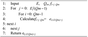
Algorithm 1. Interleaving.
Let the input bits sequence to the interleaver are denoted by e0, e1, e2, ∙∙∙, eE−1, where E is the length of bit sequence. While the interleaved bit sequence are f0, f1, f2, ∙∙∙, fE−1. The modulation order is Qm. Then the equation for calculating the index of the interleaved bits is illustrated in Algorithm 1.
The LabVIEW code of interleaver which implements Algorithm 1 is shown in Figure 8. The outer loop’s iteration represents j which starts from zero to E/(Qm − 1). While the inner loop, the iteration depends on i which starts from zero to Qm − 1. By deploying i, j in previous equation, we get fi+j ∙ Qm = f0, f1, f2, ∙∙∙, fE−1.
The calculated index is then inserted to “index array” function to extract the interleaved bit. The output interleaved bits are concatenated to form the interleaved output array.
The de-interleaving process reverts the original order of each interleaved bit. This process depends on a simple equation to extract the original index before interleaving. Algorithm 2 illustrates how to revert the original bits.
Figure 9 shows the LabVIEW implementation of Algorithm 2. As the interleaving process, the de-interleaving is implemented by changing the equation of the index. The iteration of the outer loop j starts from zero to Qm − 1 while the inner loop i starts from zero to E/(Qm − 1). The index is calculated through the equation: ei.Qm+j where e(j.E/Qm)+i = e0, e1, e2, ∙∙∙, eE−1. This index is then inserted to the “index array” function to get the de-interleaved bit.
3.6. Scrambling
The data scrambling process is done by encoding the sent message from the transmitter, to make the message unintelligible for the receiver that is not equipped with an appropriately set descrambling device or decoding algorithm needed to decode the received message.
The scrambling process in 5G is almost similar to that in LTE. We use pseudo-random sequence c(i) of gold code. Gold code is a code generated by XOR-ing two m-sequences, each m-sequence is obtained using Fibonacci LFSR, and defined by a length-31 Gold sequence. For the first m-sequence we’ll use the following relation:
(4)
![]() Algorithm 2. De-interleaving.
Algorithm 2. De-interleaving.![]()
Figure 8. LabVIEW implementation of interleaving.
![]()
Figure 9. LabVIEW implementation of De-interleaving.
where Nc = 1600. This relation leads to the following polynomials for the first and second m-sequences respectively
(5)
(6)
The first m-sequence is initialized with x(0) = 1, x(n) = 0 where n = 1, 2, 3, ∙∙∙, 30; the initialization of the second m-sequence is denoted by Cinit for PDSCH channel which obtained according to the following equation:
(7)
where nRNTI is Radio network temporary identifier, and it must be in the range of [0, 65, 535] depending on the usage of the cell. We’ll use C-RNTI (Cell RNTI) as we are using the cell in transmission to a specific user. While “q” is the code word number.
After the two m-sequences are generated, they are XOR-ed together to generate the gold code which also known as the scrambling code or the scrambling sequence. The gold code is then XOR-ed with the input data at the transmitter. At the receiver, the scrambled data is XOR-ed with the gold code so we can retrieve the data from the sender again.
Scrambling LabVIEW implementation: The Scrambling process can be simply done on LabVIEW mainly by using shift registers for the generation of the m-sequences and then XOR-ing it with the other m-sequence. The output stream bits are finally XOR-ed with data to be sent or the received.
3.7. Modulation Mapper with NOMA
The basic idea behind NOMA is superposition process in transmitter and successive decoding in the receiver to cancel interference induced from paired users. As the signals of multiple users are paired and transmitted simultaneously on the same time and frequency resources, a new domain, i.e. the power domain, is utilized by the NOMA scheme to multiplex multiple users. According to 3GPP specs, OFDMA will be used in resources division in frequency and time domain while the paired NOMA users will be super positioned in power domain. The multiple users’ signals are paired at each OFDM subcarriers. So the NOMA is superimposed in LTE OFDM system by superposition the paired signal before OFDM stage. In normal OFDM system, the modulated signal from one user is mapped to certain resource element in the modulation mapper, while in NOMA system, a paired modulated signal from two users (or may be more) is mapped in the modulation mapper.
At the receiver side, Successive interference cancellation (SIC) techniques can be used to separate and decode the superposed signal induced from multiple users. In our proposed scenario, NOMA is deployed on the PDSCH with two paired users. So superposition process is implemented in gNB side while SIC is implemented in UE side. The signal power of the paired users should properly allocated according each user channel gains to ensure successful decoding superposed signal. More specifically, more power should be allocated to user with lower channel gain (QPSK user), while less power is allocated to user with higher channel gain (16 QAM user). Let α be the power allocation factor to higher channel gain user (16 QAM user), so (1 − α) be the power allocation factor to lower channel gain user (QPSK user). The proper allocation of signal power for both users guarantees the QPSK user successfully decodes his signal. On the other hand, to decode 16 QAM signal of the second user, the QPSK signal should be firstly decoded and cancelled from the superposed signal. Then the 16 QAM signal is decoded.
LabVIEW Implementation of NOMA Modulator: To deploy the superposition coding in the transmitter in LabVIEW, new communication modules are introduced in gNB. In implementing PDSCH of our NOMA model, two modulation modules are used for the paired users instead of unique modulation module in the ordinary LTE system. As illustrated in Figure 10, a far user (UE1) is modulated using QPSK modulator and near user (UE2) is modulated using 16 QAM modulator. The modulated symbol from the paired users are superposed (with different power level) and mapped to the same resource element and then modulated to OFDM symbol.
Figure 11 depicts the recourse element mapping block which adds the symbols of the two users into one recourse element.
The output of resource element mapper is applied into OFDM modulation which makes inverse fast Fourier transform (IFFT) and adds cycle prefix. A header, tail and training sequence are added to OFDM signal to successfully decode it at receiver side.
Finally the OFDM signal passes through pulse shaping block to keep the inter symbol interference caused by the channel in control and make the signal fit in its frequency band. The Tx apply channel block makes the symbols ready to send to channel.
Figure 12 illustrates the constellation of the superposed signal which is similar to constellation of 64 QAM.
![]()
Figure 10. NOMA modulation with QPSK and 16 QAM users.
![]()
Figure 12. Constellation of super position signal.
LabVIEW Implementation of NOMA Demodulator: The block diagram of receiver is shown in Figure 13. The data received by the user’s antenna is passed through matched filter that recovers the received waves by extracting the known waves after being contaminated by noise in channel. So it improves the signal to noise ratio (SNR) and the signal detection.
OFDM synch is used to achieve symbol timing and frequency offset. Since the transmitter and receiver do not have a common time reference as the local oscillator of the transmitter and receiver could have some shifts in frequency or phase by some parts of million, so receiver needs to find symbol boundaries to avoid inter symbol interference. Beside symbol timing and frequency offset, OFDM synch is used to detect the start and the end of each frame (frame detection).
OFDM channel estimation is based on minimum mean square error (MMSE) technique. Channel estimation is necessary as it removes the effect of impairments caused by frequency selective fading.
Strip control block simply removes header and tail control information as training sequence and zero pads to recover the data.
OFDM demodulate block demodulate the received samples.
Finally, the decoder block maps the received stream of complex symbols to the corresponding binary values of each user according to the modulation used by the user.
This block is developed in 5G to suit superposed NOMA signal transmitted by paired users.
Far Receiver (QPSK): The processing procedures of the two UEs in the receive path are different. The far QPSK user directly decodes the superposed signal as the current OMA LTE receiver. The added signal from 16 QAM user is treated as a noise. In order to successfully decode the QPSK signal, the allocated gain to QPSK signal should be higher enough to maintain the received signal (which consists of superposed signal and estimated channel noise) still exists in the correct constellation part. Figure 14 illustrates the basic block diagram to modulate the QPSK user’s data.
Near User Receiver (16 QAM): Different from the QPSK far receiver, an additional SIC process is conducted to the 16 QAM near receiver. The SIC in the 16 QAM receiver firstly decodes the received superposed signal exactly as the same as the UE1 receiver extracts QPSK signal. Decoding QPSK signal for 16
QAM user is even easier than QPSK user as the user is more close to gNB than QPSK user. The QPSK signal is then subtracted from the superposed signal with same gain level it super positioned at transmitter in order to decode 16 QAM signal. So the QPSK signal should pass through the same process as in the transmit path at gNB before subtraction process. Then the UE1 signal is modulated again using QPSK modulator and cancelled from superposed signal as shown in Figure 15. The subtraction process is done by subtracting every symbol sent by the transmitter, from each symbol of QPSK far user’s symbols. The most subtraction value near zero is where the symbol of the near user is detected and this process happens on the whole 64 symbols to end up having the symbols on 16 QAM constellation of UE2.
4. Experimental Results and Analysis
The proposed 5G prototype is implemented using general purpose computers with USRP 2920. The experiments are carried out according to the proposed model explained in section II. Two users are being emulated along with a gNB. UE1 is the cell edge user and could be assigned only lower modulation scheme such as QPSK modulation while UE2 is the cell core user that is assigned higher modulation technique such as 16 QAM or 64 QAM. The two users use a downlink channel of PDSCH at the PHY layer. In these experiments, the proposed prototype operates in the FDD duplex mode and the SISO transmission mode. The DL carrier frequency is 2.66 GHz (band 7), and the system bandwidth is 5 MHz.
The proposed prototype is verified with two phases: the first is per module verification and the second is overall system verification. In the first phase a loopback test is deployed at each module in the transmitter and the appropriate one in the receiver. In the second phase, the overall system is tested.
Both simulations using SDR and experiments using USRP are carried out for model verification and system evaluation purposes.
In the simulation, the PDSCH of the paired users is implemented on the proposed prototype. Additive white Gaussian noise (AWGN) channel model is being used to emulate channel impairments for the receiver. Since each user is located
![]()
Figure 15. SIC in 16 QAM demodulator of NOMA.
at different position and different distances from the gNB, so they suffer from different channel conditions. Thus, they have different Eb/N0 values at the receivers.
Firstly, we tested the constellation diagrams of the transmitter to verify that the transmitted symbols are represented in 64 symbols as shown in Figure 16. The transmitted constellation represents symbol energies of both users after being added by the superposition-coding block at the transmitter. We set the power allocation to 0.7 dB and 0.3 dB for the QPSK & 16 QAM respectively.
Then we tested the constellation diagram of both users at receiver before adding the AWGN channel and proved that the concept of SIC at the 16 QAM is correctly designed. Figure 17 shows that the data is retrieved correctly for both users.
After that we added the channel impairments represented by the AWGN channel block that is responsible for emulating the channel noise. We set the normalized signal-to-noise ratio (SNR) to 28 dB for both users. We evaluated the performance of the complete system by using different power allocations factors α. We start the experiments with lower power allocation factor then raise it gradually.
The power allocation factor has significant effect on the performance of each user receiver. In addition, the selected modulation scheme for each user also affects the performance of the receivers. QPSK has higher performance concerning
![]()
Figure 16. Transmitted constellation diagram of both users.
![]()
Figure 17. QPSK and 16 QAM constellations diagram at receivers in perfect medium.
the BER but it has less data rates compared to the higher modulation schemes. gNB is responsible for deciding the modulation schemes for each user according to their channel quality. In general, it is noted that QPSK signal can be easily detected as observed from following constellations. Whereas at very low power allocation factor, the 16 QAM receiver cannot detect its data from the combined data as 16 QAM has higher BER.
Figure 18 illustrates the constellation of both QPSK and 16 QAM at α = 0.1. The QPSK user could easily detect its data from the combined signal enjoying high power gain (1 − α = 0.9) and so it has the lower BER when comparing with higher power allocation, while that 16 QAM signal cannot be detected.
To be able to successfully decode 16 QAM signal, the value of the power allocation factor α is increased and the resulted constellation is observed. It is noted from Figure 19 some sorts of improvements in constellation of 16 QAM signal and it can be detected.
The channel quality plays substantial role in selecting the power allocation factor of each users. We studied the resulted BER versus Eb/N0 at specific power allocation factors. Figure 20 illustrates the results at very low power allocation factor (α = 0.1). It can be noted that 16 QAM signal faces high BER and it cannot
![]()
Figure 18. Constellation diagram of QPSK and 16 QAM after SIC with α = 0.1 and Eb/N0 = 28 dB.
![]()
Figure 19. Constellation diagram of QPSK and 16 QAM after SIC with α = 0.3 and Eb/N0 = 28 dB.
be detected except at very good channel situation (Eb/N0 > 35 dB). On the other hand, QPSK enjoys low BER even at lower Eb/N0. There are some sorts of improvements in the BER versus Eb/N0 graph for the 16 QAM user as the power allocation factor increases. While the BER of QPSK receiver increases with increasing of power allocation factor as shown in Figure 21 and Figure 22 with α = 0.2 and 0.3 respectively.
We conclude that the impact of the power allocation factor α varies according to the deployed modulation scheme. The BER is improved for 16 QAM with increasing α while it’s degraded for QPSK. We can observe that 16 QAM users are more sensitive to the variation in α. Thus, to employ NOMA in a practical network, the power allocation factor and the modulation scheme for paired users should be selected in accordance with channel quality and specific tuning should be adopted for the paired users together. To get best performance for both users, it is recommended to start with lower values (where 16 QAM users cannot be detected) and increase α step by step till the 16 QAM is detected. This can be achieved by adding some additional signaling to the adaptive modulation and coding (AMC) procedure of the current LTE specifications. For example, the gNB may distribute the power in different UEs dynamically based on their channel quality indicator (CQI). Furthermore selecting the paired users should be optimized in the overall network. We can see from the experiment that if the 16 QAM enjoys good channel situation, lower values of α can be selected and so it can be paired with QPSK user with very bad channel situation and vice versa.
Real time experiments: More development is needed for the current deployment of 5G prototype in order to run in real time. So we consider an offline experiment
to evaluate the over-the-air performance of 5G. In this offline experiment, a computer and USRP is acting as gNB which generates the superposed signal of both QPSK and 16 QAM users. The simulation designed program of LabVIEW produces the signal which is dumped to a file which is then put into the gNB using Ethernet link and transmitted over the air interface with the aid of the USRP. Another computer and USRP is acting as a receiver. The received signal is dumped to a file which is sent to the computer to decode the signal. The simulation program of the first user is used to decode the signal of the QPSK user. Figure 23 illustrates the constellation of QPSK user which can be easily decoded. On the other hand Figure 24 depicts the constellation of the 16 QAM user which needs more development in the SIC parameters to successfully decode it.
One of the main issues to be considered when deploying 5G using SDR tools is the SDR memory. The SDR memory should be large enough to handle big volume of data. For example with traditional LabVIEW, only small volume of data can be transmitted without program crashing. The small volume of data affects the results severely. For example, the LDPC BG 2 cannot be tested as it is assigned only for big volume of data. The segmentation block is not practically used as the sent data is smaller than the code block size. With limited memory capability SDR, each block can be tested separately by a big volume of data, and the complete system can runs with only small volume of data. In addition, using
![]()
Figure 24. Constellation diagram of 16 QAM after SIC.
LabVIEW will not provide accurate results due to the rounding of values of BER smaller than 10−3.
5. Conclusion
5G is witnessing a remarkable development and rapid growth in data rates and applications in recent years. New technologies and techniques are introduced in 5G new radio to fulfil these demands. NOMA is a candidate radio access techniques for enhancing spectral efficiency and increasing system capacity. LDPC is a channel codding scheme that provides better network throughput according to channel condition than that provided with turbo code. SDR is a general purpose processor that allows fast prototyping on a flexible platform. In this paper we use SDR to build an open source platform to realize the transceiver of the PDSCH of 5G NR according to 3GPP specs. The built system contains the advanced techniques elected for 5G like NOMA and LDPC. Using these techniques leads large modifications in all previous and subsequent modules in 5G NR. So we implement a LabVIEW code word-level for all communication modules of NR starting from CRC, segmentation and LDPC channel coding ending with NOMA and OFMA stages. Finally, several experiments were carried out with our developed NR 5G system to evaluate its performance in practical environments. In the link-level simulations, the modulation scheme and power allocation factor for UEs have a significant impact in the SIC processing of signal decoding.