Received 23 July 2016; accepted 26 August 2016; published 29 August 2016

1. Introduction
Beam theory is often used in the analysis of many structures in the initial design stage, including machinery, ships, and vehicles. Because beams are three-dimensional (3D) elastic bodies, their behavior must be calculated on the basis of 3D elasticity theory if it is to be calculated precisely. However, there are several difficulties involved in calculating an exact solution. Thus, current beam theory is systematized under the assumption that beams are long, thin structures, with cross-sectional dimensions that are very small with respect to their lengths [1] . This theory for the beam was derived from the assumption of the cross-section invariant. Several geometric constants are very important when performing analysis based on the beam theory: these constants are cross- section-specific and are determined by the crosssection’s shape and dimensions.
One of these constants is the shear center, defined as the point at which a beam’s flexural deformation can be separated from its torsional deformation. The shear center is significant for the mechanical behavior of beams, and so it must be determined correctly in advance of analysis. Various definitions of the shear center discussed in Fung [2] . Namely
1) Setting the shear center as the point of action of the resultant of the shearing stresses in the section;
2) Setting the shear center as the point of the torsion-free bending on the basis of the strain energy considerations [3] ; and
3) Setting the shear center as the point where, in the flexural-torsional problem, the axial force of the torsion arise [4] .
However, it is difficult to accurately determine the location of the shear center in beams of arbitrary cross- sectional shapes; the cross-sectional shapes for which it can be determined are quite limited. Thus, a practical calculation method is sought that can determine the shear center and other cross-sectional constants for beams of arbitrary cross-sectional shape. Analysis using the finite element method (FEM) is practical and useful, and extremely beneficial in the initial design of beam structures based on beam theory. IN [5] , Katori has proposed a method to determine the shear center of the thin-walled cross-section by FEM.
Therefore, starting with the assumption of the cross-section invariant, we show here a practical, FEM-based calculation method for determining the shear center of a beam of arbitrary cross-sectional shape. The first, we discuss the shear-torsion coupling problem for beams of arbitrary cross-sectional shape based on Saint-Venant’s theorem [6] . In order to determine the relationship between shear deflection and shear force in this coupling problem, we treat it as a stationary value problem with subsidiary conditions, and derive simultaneous equations for warping, shear deflection, torsion angle, and undetermined Lagrange multipliers by means of a finite element approximation. We then solve this to derive a 3 × 3 matrix of flexural rigidity versus torsional rigidity represent- ing the coupling of shear deflection and torsion. We determine the shear center by defining the coordinate axis such that the elements representing the coupling of shear and torsion in this matrix, (1, 3) and (2, 3), become zero.
2. Theory
2.1. Finite Element Analysis of the Shear-Torsion Coupling Problem in Beams
In a straight beam of uniform cross section of the type shown in Figure 1 is considered. The x-axis is the longitudinal centroidal axis, while they- and z-axes are set according to the right-handed system. In bending of beam, the cross section remains plane as is assumed in the elementary theory. Vlasov is the assumption of the cross section invariant is the starting point. Here, we formulate our equations based on his assumption of the cross section invariant. This assumption can be made from two standpoints: 1) the assumption of rigid cross sections and 2) the assumption of planar stress-free cross sections. Here, the taking assumption of rigid cross sections. therefore, we make the following reasonable assumption: the strain components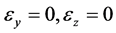 , and
, and  at all points in the beam. Based on this assumption, deriving the directional displacements v and w in the y- and z-axes at an arbitrary point on the beam gives us the following:
 (1)
(1)
where  and
and  are the displacement components of the centroid in the y and z directions, and
  is the angle of rotation of the cross section about the x-axis.
Next, an x-axis displacement of the beam should accompany the cross-sectional displacement given by Equation (1). This x-axis displacement is approximated over each element e by
 (2)
(2)
where u is the vector of nodal values ui of u for the element and  is a vector of the shape functions Ni.
In the following equation, the shear strains generated in the crosssection of the beam  and
and  are expressed in terms of the displacement components u, v, and w:
 (3)
(3)
![]()
Figure 1. Coordinate system of an elastic beam.
By substituting Equations (1)-(2) into Equation (3), the shear strains  and
and  can be expressed as follows:
 (4)
(4)
where a prime denotes derivation with respect to x, that is ![]() and
and ![]() and
and ![]() represent the derivation with respect to y and z of the shape function, respectively.
represent the derivation with respect to y and z of the shape function, respectively.
The strain energy U of per unit length along the x-axis is found by evaluating the following integral:
![]() (5)
(5)
The potential energy L for the external forces meanwhile is given as follows
![]() (6)
(6)
where Qy and Qz are the shear forces in they and z directions, respectively, and Mx is the torsional moment.
Let us now consider how to minimize the total potential energy ![]() under the following conditions.
under the following conditions.
The axial stress can be expressed as follows when the beam is subjected to axial forces P and moments (My, Mz)
![]() (7)
(7)
The warping u by shear and torsion is independent of the u due to axial force and bending
![]() (8)
(8)
Substitute of Equation (7) into Equation (8) and the integrals of Equation (8), in terms of the warping u, become
![]() (9)
(9)
At this time we make use of the method of the Lagrange multiplier. That is, we multiply Equation (9) by an undetermined constant ![]() (the Lagrange multiplier) and add Equation (5), (6) and (9) to get:
(the Lagrange multiplier) and add Equation (5), (6) and (9) to get:
![]() (10)
(10)
The stationary condition for ![]() in Π1 in the above equation becomes the following:
in Π1 in the above equation becomes the following:
![]() (11)
(11)
Thus,
![]() (12)
(12)
in which
![]() (13)
(13)
Writing an inverse matrix of the left-hand-side matrix of Equation (12) as
![]() (14)
(14)
Thus, according to Equation (12)
![]() (15)
(15)
From Equation (15), the following relationship can be derived easily
![]() (16)
(16)
In addition, the warping u in the x-axis generated by shear force and torsional moment can be obtained via Equation (15)
![]() (17)
(17)
2.2. Shear Center
Converting the above displacement of and force acting on the centroid to an arbitrary point (ys, zs) in the cross- sectional plane (e.g., Figure 2) yields
![]()
Figure 2. Centroid O and shear center S.
![]() (18)
(18)
Now replacing the relationship between shear force and shear deflection on the centroid in Equation (16) Using Equation (18), we arrive at the result:
![]() (19)
(19)
where
![]() (20)
(20)
The shear center is obtained by equating to zero the elements (1, 3) and (2, 3) of matrix Ds, i.e.
![]() (21)
(21)
Where Dij is the (i, j)th element of![]() , as defined in Equation (16).
, as defined in Equation (16).
3. Numerical Example
The procedures of the previous sections have been applied to two example problems. Calculations were performed using triangular linear elements, which are widely utilized in typical finite element analysis.
Example 1. Initially selecting the semicircular cross section of radius R as shown in Figure 3. We determined its shear center and compared it with other calculation results. In this analysis, calculations were performed after dividing the semicircular cross section into triangular elements, for a model with 108 nodes and 180 elements (Model I) and for a model with 186 nodes and 322 elements (Model II). Table 1 presents a comparison positions of shear center in a semicircular cross section. Assuming that in-plane stress is zero, Timoshenko determined the shear center for a corrected semicircular cross section with reference to the shear stress distribution when a concentrated load was applied to the end of a cantilever beam with a circular cross section [7] . In addition, Kawai et al. [8] determined the shear center from simple calculations based on the assumption of cross-section invariant without the need for corrections such as Timoshenko’s. Furthermore, the basic equation and boundary conditions in the shear-torsion coupling problem shown by the authors in Reference [6] are as follows:
![]() (22)
(22)
The shear center (ys, zs) is thus derived as
![]()
![]() (23)
(23)
The function ![]() satisfies Equation (22) in the case of a semicircular cross section
satisfies Equation (22) in the case of a semicircular cross section
![]() (24)
(24)
where ![]() is the position of the centroid. The position of the shear center can be determined as follows
is the position of the centroid. The position of the shear center can be determined as follows
![]() (25)
(25)
These results differ from the results of our FEM-based analysis by less than 1%, suggesting our solution has sufficient accuracy in practice.
Example 2. Determine the shear center of a circular cross section with a circular notch shown in Figure 4. Figure 5 shows the coordinates y/r for the shear center ys and centroid yc, for various ratios a/r of the radius r of the circular cross section versus the radius a of the circular notch. The figure also shows the results of the analsysis of Strongeand Zhang [9] . The resent analysis results are almost entirely consistent with theirs, supporting the validity of the present analysis method. Figure 6 shows the distribution of warping u for ratios a/r of 0.2, 0.6, and 1.0 when the torsional moment Mx has acted. Contour has become finer in the notch tip. This tendency is remarkable enough to a/r is smaller.
4. Conclusion
This paper discussed a practical calculation method to address shear-torsion coupling. Based on the FEM, we proposed a method to analyze the shear-torsion coupling problem when analyzing beams with cross sections of arbitrary shape as a stationary value problem with subsidiary condition. Specifically, we constructed simultaneous equations for strain deflection, torsion angle, warping, and undetermined Lagrange multipliers,
![]()
Figure 4. Circular cross section with circular notch.
![]()
Table 1. Shear center for semicircular cross section.
![]()
Figure 5. Coordinates of shear center and centroid of circular cross section with circular notch.
![]()
Figure 6. Warping of twisted shaft with notched circular cross section. (a) a/r = 0.2; (b) a/r = 0.6; (c) a/r = 1.0.
using finite element approximations. We then solved this to derive a matrix of strain rigidity versus torsional rigidity. This matrix represents the coupling of shear deflection and torsion: we successfully determined the shear center by defining a coordinate axis such that non-diagonal terms in it disappeared. We analyzed a simple example using a calculation program created based on this analysis, and confirmed the usefulness of this technique.
Acknowledgements
The author thanks the editor and the referee for their comments.