Chromium Electroplating of Aluminium Alloys Using Electroless Nickel as Underlayer ()
1. Introduction
The increasing need to achieve fuel economy, triggered by environmental concerns and increasing energy prices, has significantly influenced material selection during manufacture. The use of lightweight materials can help reduce vehicle weight and improve fuel economy. The weight reduction concept has driven a gradual decrease in the use of ferrous metals and the corresponding increase in the use of lightweight materials such as aluminium in the automotive industry. Manufacturers especially in the aerospace, architectural, automotive, packaging and the construction industries have gradually shifted towards the use of light alloys such as aluminium, magnesium and titanium [1] [2] . However, the poor surface characteristics of light metals have limited successfully protective coating of the substrates. Therefore, they cannot meet the requirements for durability and functionality in applications, where they are exposed to wear, corrosion and friction unless adequate surface modifications or coating is provided The aim of this study is to apply an electroless undercoat to pretreated aluminium alloys prior to a surface metallic finish with duplex nickel and chromium, in order to improve corrosion resistance of the substrate. Variants of hexavalent and trivalent chromium plating will be applied to pre-treated Al 1050 and Al 6061 following electroless nickel deposition and then characterised by surface analysis techniques. The chromium finish would also be tested for scratch adhesion, hardness and corrosion resistance.
The satisfactory provision of decorative and functional surfaces on light metals such as aluminium depends critically on the preparation of the substrate for electrodeposition [3] [4] . Electrodeposition onto aluminium poses a number of fundamental problems to the electroplater. Aluminium has great affinity for oxygen and when it is exposed to air, direct oxidation causes the spontaneous formation of a thin, compact, tough and inert film of oxide. Therefore, special pretreatment sequences are essential in order to enable aluminium substrates to be electroplated with adherent coatings. Without a full appreciation of the alloy composition and the level of heat treatment that it has been subjected to, it may be difficult to select an appropriate pretreatment sequence. A series of pretreatment procedures for aluminium and its alloys have evolved aimed at improving the levels of adhesion between aluminium and the plated metal. Immersion film, based on zincate solutions, is the most widely used technique prior to electrodeposition of metallic coatings on aluminium [3] .
Pretreatment of aluminium prior to electroplating, generally involves cleaning, etching, desmutting and zincating. Alkaline process solutions are effective in removing oxides from aluminium surface, because aluminium oxide is more soluble in alkali than in acid. The most common pretreatment method currently used is to directly electroplate nickel onto the aluminium substrate. However, nickel electroplating can lead to problems due to unsatisfactory deposits in low current density areas (complex geometry).
Since aluminium is less noble than chromium in the passive state, there is a risk of an accelerated corrosion of the aluminium substrate plated with a thin decorative deposit of chromium without a prevailing intermediate layer. Hence an under layer of copper or nickel or both would need to be applied on aluminium (in pure or alloy form) before chromium coating [5] . Takacs et al. [6] studied the effects of pre-treatment on the corrosion properties of electroless Ni-P layers deposited on AlMg2 alloy. Using a measure of polarisation resistances, they found that the nickel pre-coating and the hypophosphite adlayer formed by suitable immersion pre-treatments improved the corrosion resistance of the samples immersed in aerated sodium sulphate solution. They attributed the decrease in corrosion resistance to the lower micro porosity and smoother morphology of the nickel-phosphorus coatings. In another study, Hino et al. [7] , researched on the effects of zincate treatment on adhesion of electroless Ni-P coating on various aluminium alloys. They concluded that initial zinc deposition on the surface is an important factor influencing the morphology of the second zincate deposit and its adhesion.
The plating industry also faces a problem with chromium plating of aluminium in the light of legislation restricting the use of hexavalent chromium in the plating industry. Voorwald et al. [8] studied the effect of electroless nickel interlayer on the fatigue strength of chromium electroplated AISI 4340 steel. They concluded that the hard chromium electroplating showed excellent adhesion when applied on steel, as well as on the electroless nickel plating. It was also established that the nickel interlayer was able to inhibit or retain the propagation of many original cracks from the hard chromium external layer to the substrate. Hamid and Elkhair [9] have developed electroless nickel-phosphorus composite deposits for wear resistance of Al 6061 while Wu, Zhao, Xie and Yang [10] have reviewed electroplating and electroless plating on Magnesium alloys. Khan et al. [11] reviewed regulatory, technical and economic issues involved in replacing hexavalent chromium plating as stringent restriction legislations have been introduced to phase out hexavalent chromium or limit its use in the plating industry. A promising alternative to hexavalent chromium plating [12] is trivalent chromium plating.
Figure 1 shows samples of failed electro and electroless nickel depositions as a result of inadequate pretreatment of the aluminium alloy substrate showing blisters, delamination and detached deposition.

Figure 1. Failed nickel deposition on pretreated Aluminium Alloys [13] 1000× magnification.
2. Experimental Procedure
Aluminium alloys consisting of Al 1050 and Al 6061 were samples used in this study for chromium plating involving; zincating, electroless nickel deposition, duplex nickel and chromium electroplating. Samples were guillotined to size with the following dimensions: 100 mm × 100 mm × 1 mm for both alloy samples. Chemical compositions of Al 1050 and Al 6061 have been presented and discussed in Aluminium Federation [14] .
2.1. Procedures for Sample Preparation/Plating
Figure 2 shows the research methodology adopted for chromium electro plating of aluminium alloys. The process starts with pretreatment of samples using the zincating process which involves cleaning, etching, desmutting and zincating. The zincate removes oxide layer and minimises re-oxidation of sample surface before duplex nickel and chromium are deposited onto the alloys. The operating conditions used were based on the Bondal process [15] for pretreatment of aluminium alloys as recommended by MacDermid, using Minco cleaner [16] and 66-Microetch [17] .
The next stage after zincating involves plating nickel as an undercoat prior to chromium deposition. In this study the option of applying electroless nickel for nickel deposition on the substrate was considered which was deposited at the rate of 15 - 20 micron-hr using commercial solution VAND-ALOY 6000 [18] , formulated in sodium hypophosphite as the reducing agent and other additives.
Semi bright nickel (maximum of 0.005% sulphur) deposited to a thickness of 60% - 75% is generally used in combination with bright nickel to achieve a robust corrosion protection of the metal. The rationale for this approach is that bright nickel which is less noble than the semi bright nickel layer corrodes preferentially, and there by protects the substrate. Proprietary solutions NiMac SF`[19] , NiMac Clarion II formula [20] were used for semi bright [17] and for bright nickel deposition, while NiMac Hypore XL [21] was used for microporous nickel deposition.
Finally, chromium plating is achieved by depositing 0.5 um of chromium over thin microporous nickel (nickel thickness of lum), thus preventing rapid local corrosion. This study was able to apply both hexavalent and trivalent chromium plating on the samples based on formulation by MacDermid Plc, while proprietary solution Mach II [22] was used for hexavalent chromium deposition, TriMac III [23] trivalent chromium was used for trivalent chromium plating. Overall, four variants for chromium plating were adopted as follows.
Pretreatment/Duplex nickel/Microporous nickel/Hexavalent chromium
Pretreatment/Duplex nickel/Microporous nickel/Trivalent chromium
Pretreatment/Electroless nickel/Duplex nickel/Microporous nickel/Hexavalent chromium
Pretreatment/Electroless nickel/Duplex nickel/Microporous nickel/Trivalent chromium Details of procedures for plating electroless nickel, microporous nickel, semi bright nickel, bright nickel and chromium on to aluminium samples have been described by Khan [13] . TriMac III, a proprietary solution MacDermid [23] was used for trivalent chromium. The chemical composition and operating conditions of TriMacIII are as follows.
TriMac III conductivity salts 250 - 320 g/L Total chromium metal 10 - 20 g/L Temperature 50˚C - 65˚C pH 3.2 - 3.8 Cathode current density 7 - 15 A/dm2
Voltage 12 Volts Agitation Mild air agitation or gentle solution movement
 (a)
(a) (b)
(b)
Figure 2. (a) Summary of Research Methodology for Chromium Plating of Aluminium Alloys; (b) Flow chart for duplex nickel/chromium coating of Al samples with the option of electroless nickel undercoat [13] .
2.2. Procedures for Sample Testing after Chromium Plating
2.2.1. Copper Accelerated Salt Spray Test (CASS)
Corrosion testing of variant chromium plated Al 1050 and Al 6061 samples was carried out using copper accelerated acetic acid salt spray test (CASS). The copper accelerated acetic acid salt spray test was developed specifically to test nickel/chromium and copper/nickel/chromium electrodeposited coatings and it is also used to determine the corrosion resistance of various aluminium alloys [24] . The copper-accelerated acetic acid salt spray test (ASTM, B-368) is more rapid than the acetic acid salt spray test (ASTM, B287) and has been used in many automotive applications.
2.2.2. Scanning Electron Microscopy (SEM)
A ZEISS EVO scanning electron microscope 60 series interfaced with smart SEM software was used with a resolution of 3.0 nm at 0.2 - 30 KeV acceleration voltage and a magnification of up to 5 - 1,000,000× with 3072 × 2304 pixel images [25] . ZEISS EVO scanning electron microscope 60 series interfaced with smart SEM software was used to examine immersion deposit on Al 1050 and Al 6061 alloys cross sectional chrome plated samples and after 96 hours of CASS test. It has a resolution of 3.0 nm at 0.2 - 30 KeV acceleration voltage. A magnification up to 5 - l,000,000× with 3072 × 2304 pixel images could be achieved [26] .
2.2.3. Atomic Force Microscopy (AFM)
The atomic force microscopy technique was carried out on four coatings on Al 1050 and Al 6061. The chromium electroplated samples were examined using the Thermo Microscope and MS Interface Module atomic force microscope. The most common statistical parameters obtained from atomic force microscopy were Ra (the average roughness deviation) and Rms (the root mean square roughness deviation) respectively. Ra and Rms values for the four different coatings onto Al 1050 and Al 6061 were calculated from topographical data using SPMLab 5.01 software. Atomic force microscopy produces images by recording interaction forces between the apex of probe tip and atoms present at the sample surface as the tip is scanned over the surface of the sample [27] [28] .
2.2.4. Linear Sweep Voltammetry
A potentiostat (EG + G Instruments, Model 263A) with three electrode arrangement was used to determine the corrosion current density (Icorr) using linear polarization [29] . This was carried out in 5% neutral sodium chloride solution using a Ag/AgCl reference electrode over a potential range of +/− 20 mV vs open circuit potential. The equilibrium time that the 1 cm2 surface of panel is in contact with the NaCl, was varied between 30 and 60 minutes to record polarisation resistance of the chromium coated samples. The electrochemical corrosion test was carried out on chromium plated samples using linear polarization technique to derive the Icorr values.
2.2.5 Scratch Adhesion Testing
Adhesion test for variants of chromium deposits was carried out using the scratch tester ST 30 (with a diamond indentor, a cone angle of 120 degrees, tip radius of 0.2 mm and load range of 1.0 - 200.0 N) designed to characterize the adhesive strength of coatings deposited on flat substrates (Stallard et al. [30] ). The scratch tester enables measurement of the critical load at which a coating first shows signs of failure. Adhesion testing was carried out with single pass under progressive loading of 0 - 200 N with a scratch speed of 5.0 - 400 mm/minute. The indentor tip was drawn across the coatings with a loading rate of 100 N/mm and a sliding speed of 10 mm/min. Measurement of the total length of the scratch and distance along the scratch at which the failure first occurs enables the critical load of the coating to be calculated recorded as the normal force at which the damage was first observed [31] . The lower critical load is defined as the load at which initial coating failure is detected, the upper critical load is that where significant damage is apparent and the coating is no longer suited for its intended use [32] . Figure 3 shows evidence of coating failure both at first and second critical loads.
2.2.6. Vickers Hardness Testing
Universal Vickers hardness testing on chromium deposits was carried out using Zwick Roell-Z20, 20 KN materials testing machine interfaced with X-pert software. The software monitors and controls hardness testing characteristics such as nominal force, travel speed range, mounting height, and calibration factors. Test loads, and indentation depth are used to calculate coating hardness (Zwick Roell Hardness testing). A defined load is applied through Vickers diamond indenter pressed into tested samples. Vickers Hardness Number (VHN), is obtained as the load divided by the surface area of the indentation. According to Chandler [33] , Vickers Hardness Number (VHN) is expressed as:
 (1)
(1)
where “P” is the applied force in kg and “L” is the average length of diagonals.

Figure 3. Evidence of coating failure through complete coating removal (Dryda and Sayer) [33] .
3. Results
3.1. Surface Characterization of Chromium Electroplated Al 1050 and Al 6061
Atomic force microscopy was carried out on eight variant chromium coatings of Al 1050 and Al 6061. Figure 4 and Figure 5 show sample micrographs obtained from scanning an area of 100 µm by 100 µm of chromium electroplated samples. Figure 4 clearly shows microcracks and minor inclusions on duplex nickel/hexavalent chromium deposited onto Al 1050. The presence of microcracks could be as a result of residual tensile stress especially at thicknesses exceeding 0.8 microns. However, chromium deposition on Al 1050 and Al 6061 appear to have better surface characteristics compared to the over thirty microcracks per sq-mm observed on deposits from a hexavalent chromium electrolyte bath according to Dennis and Such [5] and Snyder [30] .
Variant coatings of Al 1050 and Al 6061 were studied to quantify surface roughness using atomic force microscopy. Table 1 shows average roughness and root mean square roughness values (measured in nanometers) obtained from four variant chromium coatings on the samples. The average (Ra) value for duplex nickel/hexavalent chromium deposit on Al 1050 was 0.065 nm, while the average (Ra) value for duplex nickel/trivalent chromium deposits onto Al 1050 was 0.092 nm. The average roughness (Ra) value for duplex nickel/hexavalent chromium deposit on Al 6061 was 0.036 nm compared to the trivalent which was 0.033 nm. The root mean square roughness values calculated for Al 1050 and Al 6061 showed similar trends to the surface roughness. Overall, the conclusion from the study was that average roughness and root mean square roughness values were comparatively higher for Al 1050 than for Al 6061 while trivalent variants showed higher surface roughness compared to the hexavalent variants. The results also show that surface roughness may be influenced by the undercoat since roughness was lower in the variants with electroless nickel undercoat.
3.2. Cross-Sectional Evaluation of Variant Chromium Coatings on Al 1050 and Al 6061
The highly reflective nature of chromium deposits made it difficult to characterise plain view images of the

Figure 4. Atomic force microscopic image of duplex nickel/ hexavalent chromium (1 micron thick, ×2.5 K) for Al 1050 (Force volume scan 10,000 µm).

Figure 5. Atomic force microscopic image of duplex nickel/hex-avalent chromium (1 micron thick, ×2.5 K) for Al 1050 with electroless nickel undercoat (Force volume scan 10,000 µm).
samples using atomic force microscopy. For instance it was difficult to identify pores, cracks, and the different layers of nickel and chromium from the deposits. Scanning electron microscopy technique therefore was used to view cross sections of chromium deposits on the samples. Figure 6(a) shows a cross section of duplex nickel/hexavalent chromium deposition on Al 6061, while Figure 6(b) shows the same sample with electroless nickel undercoat. The figures show distinct layers highlighting the thicknesses of semi bright nickel and bright nickel measuring 25 μm and 15 μm respectively. Figure 7(a) and Figure 7(b) also show duplex nickel/trivalent chromium deposit and the variant with electroless nickel plating respectively measuring approximately 5 μm thick.
 (a)
(a) (b)
(b)
Figure 6. (a) SEM of cross section of duplex nickel/hexavalent chromium plated onto Al 6061; (b) SEM of cross section of duplex nickel/hexavalent chromium plated onto Al 6061 with electroless nickel undercoat.
 (a)
(a) (b)
(b)
Figure 7. (a) SEM of cross section of duplex nickel/trivalent chromium plated onto Al 6061; (b) SEM of cross section of duplex nickel/trivalent chromium plated onto Al 6061 with electroless nickel undercoat.
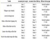
Table 1. Data for atomic force microscopy showing average and root mean square roughness values obtained for chromium plated Al 1050 and Al 6061.
3.3. Scratch Adhesion Testing of Variant Chromium Coatings on Al 1050 and Al 6061
Scratch adhesion tests were carried out on variant chromium coatings on Al 1050 and Al 6061 samples to characterize the adhesive strength of coatings deposited. Figure 8(a) and Figure 8(b) show the graphs of frictional force, first derivative of frictional force and acoustic emission plotted on the Y axis against the applied load on the X axis for Al 1050 without and with electroless nickel undercoat respectively. Adhesion of chromium coating was dependent on forces due to Van der waals’, electrostatics and chemical bonding. Frictional force increased with load applied until the first critical load (Lc1) was reached when the first damage occurred at 85 N for duplex nickel/trivalent and the second critical load (Lc2) was reached at about 135 N.
The scratch adhesion test is influenced by a number of intrinsic and extrinsic factors which are not adhesion related [34] . The stress developed around an indentor in scratch adhesion testing of a chromium coating is very complex and it is difficult to determine the stresses which caused the detachment of the coatings. The mechanism for scratch testing from SEM micrographs shows that buckling is developed at the head end of the crack followed by chipping which continues along the scratch channel. The high critical load obtained with duplex nickel/chromium coatings confirmed that damage occurred at a higher than normal load. Uniform and conformal shapes were observed across the scratch length after the scratch adhesion tests. This indicates that the coatings are capable of absorbing energy of the indentation due to their elastic/plastic behaviour. A mixture of concave and convex shapes are observed in the middle of the scratch, where the cracks seemed to be deeper. These results confirm that the coatings can not easily undergo delamination and flaking even at higher than normal loads.
Table 2 shows the first and second critical loads obtained from the scratch adhesion test. In all cases studied, Al 1050 showed higher first and second critical loads compared to Al 6061. It also appeared that trivalent coating was more adherent compared to the hexavalent coating.
The scratch test has been used to assess the adhesion of thin hard coatings and is a useful tool for coating development for quality assurance. Previous research confirms that the test is influenced by a number of intrinsic and extrinsic factors which are not adhesion-related and the results of the test are usually regarded as only semi-quantitative (Bull and Berasetegui, 2006) [33] . The stress state around a moving indenter scratching a coating/substrate system is thought to be very complex and therefore, it is difficult to determine the stresses which lead to coating detachment. It is thought that, the interfacial defect state responsible for failure is unknown, however, by careful analysis of failure modes in a scratch test (not all of which are related to adhesion) it is possible to identify adhesive failures.
Figure 9 shows the load depth profile for 5 kg force applied on Aluminium alloy 6061 plated with Duplex Nickel Hexavalent (Figure 9(a)) and Duplex Nickel Trivalent Chromium (Figure 9(b)) deposits. It shows the load on and off cycle (cycle of loading and unloading) and the depth of indentation left on the sample. The indentation depth is measured in two forms as maximum depth achieved at applied load as well as the depth of indentation after removing the load. A load of 5 kg force left an indentation depth of 32 µm on the Duplex Hexavalent chromium variant compared to 35 µm on the Trivalent chromium plating on the alloy. Figure 10 shows the load depth profile for 5 kg force applied on the same alloy but with provision for electroless nickel undercoat below the duplex nickel. The indentation depth on the Hexavalent chromium variant increased to 35 µm while the trivalent variant increased to 50 µm. This is expected as the electroless nickel undercoat has further extended the distance from the surface of the plate to the substrate. At a 10 kg applied force (Figure 11), indentation depth increased to 48 µm for the Hexavalent compared to 80 µm for the trivalent equivalent.
Table 3 shows maximum indentation and final depth at different applied loads.
The values for indentation depth achieved in all cases show that the indenter penetrated the substrate
Indentation increased with load applied on the material
Indentation depth was much higher for Aluminium 6061 compared with Aluminium 1050
In all cases the depth after removal of indentation is lower than the original depth recorded with indentation.
In most cases, indentation depth is much higher with electroless undercoat plated below the chromium compared to the same alloy without an electroless undercoat.
Table 3 also shows Vicker hardness values calculated for the various alloys under specific loads. The hardness values are found to decrease with increasing load and in most cases hardness values were higher for Aluminium 6061 compared to Aluminium 1050. Hardness values also appeared to decrease in variants with electroless nickel undercoat compared to those without nickel undercoat.
 (a)
(a) (b)
(b)
Figure 8. (a) Plot of scratch test showing friction force, first derivative of friction test and acoustic emission for duplex nickel/trivalent chromium coatings coatings onto Al 1050; (b) Plot of scratch test showing friction force first derivative of friction test and acoustic emission for duplex nickel/hexavalent chromium coatings onto Al 1050.
 (a)
(a) (b)
(b)
Figure 9. (a) Load-depth profile for 5 kg force applied duplex nickel hexavalent chromium (Al 6061); (b) Loaddepth profile for 5 kg force applied on duplex nickel trivalent chromium (Al 6061).
Table 2. First and second critical load values obtained from the scratch adhesion test onto Al 1050 and Al 6061.
Table 3. Vicker hardness measurement for variant chromium coatings.
 (a)
(a) (b)
(b)
Figure 10. (a) Load-depth profile for 5 kg force applied on duplex nickel hexavalent chromium (Al 6061) with electroless nickel undercoat; (b) Load-depth profile for 5 kg force applied on duplex nickel trivalent chromium (Al 6061) with electroless nickel undercoat.
 (a)
(a) (b)
(b)
Figure 11. (a) Load-depth profile for 10 kg force applied on Duplex nickel hexavalent chromium (Al 6061); (b) Load-depth profile for 10 kg force applied on Duplex nickel trivalent chromium (Al 6061).
3.4. Copper Accelerated Acetic Acid Salt Spray Testing of Variant Chromium Coatings
Corrosion testing of chromium plated Al 1050 and Al 6061 samples was carried out using copper accelerated acetic acid salt spray test (CASS). Figure 12 shows photographs of chromium plated samples after 24 hours and 96 hours in the CASS test chamber. There is evidence of intense corrosion (white powder) especially after 96 hours in the test chamber.

 (a) (b)
Figure 12. Chromium plated samples photographed after (a) 24 Hours and (b) 96 hours in a CASS testing chamber.
3.5. Evaluation of Chromium Plated Aluminium Alloys after CASS Test Using Scanning Electron Microscope
Figure 13(a) to Figure 13(d) show scanning electron micrographs of cross sections of chromium plated alloy samples after 24 and 96 hours of copper accelerated acetic acid salt spray test. The results of the CASS test demonstrate the durability of the chromium coatings acting as protective layer for the substrate. The results show the level of corrosion resistance associated with the nickel/chromium coatings on both alloy samples, with and without electroless nickel deposition as undercoat.
Overall, the micrographs show some pits and pores and evidence of preferential attack on the bright nickel directly underneath the microporous chromium coatings. The pores due to corrosion appear to have penetrated more into the bright nickel layer showing a well-defined pit shape, but however, have not spread into the semi-bright nickel layer. While there is evidence of initiation and propagation of small pits beneath the chromium, these did not appear to coalesce to form large and deep craters that could result in the eventual failure of the coatings. Defects from corrosion tend to spread laterally forming cup shaped pits which are not significant and therefore are unable to form deep craters into the coatings. Both hexavalent and trivalent chromium deposit surfaces showed similar responses to the CASS test, however, the pit sizes in the case of trivalent chromium deposition were comparatively bigger.
Overall, there seem to be no visible difference in morphology between alloy variants with and without electroless nickel undercoat following the CASS test, however, electroless deposition provides an additional layer directly below the duplex nickel layer which further protects the substrate from early deterioration.
3.6. Evaluation of Variant Chromium Coated Aluminium Alloy Samples Using Linear Polarization Corrosion Resistance Measurement
Linear polarization corrosion resistance analysis was carried out to determine the corrosion current density for chromium plated Al 1050 and Al 6061 samples at the open circuit potential. Table 4 shows a comparison of Icorr values for variant chromium coatings (duplex nickel/trivalent and duplex nickel hexavalent) for samples measured at 30 min and 60 min equilibration times. Overall, Icorr values are found to increase with polarization time (compare Icorr after 30 min with 60 min) for both hexavalent and trivalent chromium variants, and also with and without electroless nickel undercoat. Data acquired for Al 1050 after 30 min and 60 min equilibration times were found to be much higher than those for Al 6061. This implies that Al 6061 was more corrosion resistant than Al 1050. Icorr data for trivalent chromium coatings including variants with electroless nickel undercoat were much higher than those for hexavalent chromium which shows that the hexavalent chromium had a lower rate of corrosion compared to the trivalent equivalent.
4. Conclusions
The study carried out here has described the development of a methodology for duplex nickel chromium electroplating of aluminium alloys with the option of electroless nickel plated as under layer to the chromium. The study has produced the following conclusions:
Table 4. Icorr values as a measure of linear polarization corrosion resistance for variant chromium coatings on Al 1050 and Al 6061.
Atomic force microscopy images for duplex nickel/hexavalent chromium and duplex nickel/trivalent chromium coatings on aluminium 1050 showed evidence of microcracks. However, this was more prominent on the hexavalent variant. The average and root mean square roughness data showed that both hexavalent and trivalent chromium coatings portrayed relatively smooth surfaces for both alloys. However, average surface roughness values for duplex nickel/hexavalent chromium and duplex nickel/trivalent chromium coatings were comparatively higher for Al 1050 than for Al 6061. There appeared to be a marginal surface roughness improvement with electroless nickel underlayer, compared to the variants without an underlayer.
SEM cross-sectional micrographs showed that the chromium layer was not affected even after 96 hours of CASS testing for both hexavalent and trivalent chromium coatings on the two alloy samples. However, tiny pits and pores were observed penetrating the bright nickel layer but only spreading laterally. There was no perceptible difference noticed between trivalent chromium platings compared to the hexavalent equivalent to draw a conclusion. However, linear polarization data confirm higher corrosion rate for the trivalent compared to the hexavalent plating. The small pits and pores did not coalesce to form large and deep craters which could generate coating failure. It could therefore be concluded that chromium coatings on both aluminium samples offered good resistance to corrosion with an electroless nickel under layer further shielding the substrate from exposure to early corrosion.
The failure mode in the scratch adhesion test started with buckling which then continued with chipping across the scratch channel. However, the surfaces observed under SEM showed that there were no signs of spallation and delamination of the coatings and confirmed that chromium coating was sufficiently adherent to the substrate. The alloy samples with electroless nickel undercoat appeared indifferently during scratch testing and therefore they were ignored as part of the results. The adherence characteristics exhibited by Al 1050 at both first and second critical loads were higher than those for Al 6061.
In most cases for Vickers hardness testing, hexavalent chromium showed higher hardness values compared to trivalent chromium plating. The average hardness values confirmed that both hexavalent and trivalent chromium coatings all decreased in hardness with electroless nickel undercoat.
The Icorr data (reflecting linear polarization corrosion resistance) obtained from electrochemical linear polarisation for both alloy samples appeared to increase with electroless nickel undercoat. Icorr values for trivalent coating were also higher than those for the hexavalent equivalent showing that the trivalent equivalent had a higher rate of corrosion. Similarly, Al 1050 showed a higher corrosion rate than Al 6061.
Acknowledgements
We wish to express our gratitude to the Engineering and Physical Sciences Research Council, UK for the sponsorship of this project and to MacDermid Plc for providing some of the materials and equipment used in this study.
NOTES
*Corresponding author.