Maximum Power Point Tracking Control Using Neural Networks for Stand-Alone Photovoltaic Systems ()
Table 2. Electrical power system parameters.
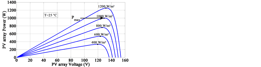

Figure 6. Simulated P-V and I-V characteristics of the PV array at constant temperature.
 (17)
(17)
where  is the number of patterns,
  is the
  measured optimum voltage by true MPPT of the PV array; and
  is the
  estimated optimum voltage with NN of the PV array. The MBE gives an indication of the average deviation of the estimated values from the corresponding measured data. A positive MBE value indicates the amount of overestimation in the estimated data and vice versa. Finally, the RMSE represents a measure of the variation of estimated values around the measured data [10] . The expressions of MBE and RMSE are expressed as follows [13] :
 (18)
(18)
 (19)
(19)
In our work, 800 couples of solar radiation and ambient temperature were used during the training process of the ANN; however, the test set (175 couples) is made up of data that the network has never seen. The obtained values of the statistical parameters are 0.32% (APAE), 0.085% (MBE) and 0.38% (RMSE). It can be concluded that once the ANN has been trained, it is able to estimate the maximum voltage corresponding to the MPP even for the data not used during the training process with an acceptable accuracy. Figure 8 shows the measured optimum voltage with true MPPT and the NN estimated optimum voltage for 175 solar radiation and ambient temperature records, as can be seen; there is a good fit between measured data and estimated data.
The next simulation aim is to present the electrical behavior of the photovoltaic system; this latter is composed of a PV array, a buck converter and a battery connected in parallel with a constant resistance load as defined above in Figure 1. We carried out a first series of tests in which the PV array is exposed to illumination varying from 550 to 1050 W/m2 and then to 550 W/m2. We show in Figure 9 the illumination profile considered in this test. The temperature is maintained constant at T = 25˚C.


Figure 7. Simulated P-V and I-V characteristics of the PV array at constant solar radiation.

Figure 8. The neural network response and the corresponding targets for the test set.
We show in Figures 10-12 the dynamic responses of the PV system driven by the MPPT algorithm in terms of generated output power, voltage and current.
With reference to Figures 10-12, we observe that the obtained response curves show a fast response time (less than 0.1 sec.) offered by proposed MPPT control unit to irradiance changes, to track accurately and maintains the real MPP after each step of irradiation variation, thus a good stabilization is obtained. We can also conclude

Figure 10. The output power of PV array based on MPPT control.

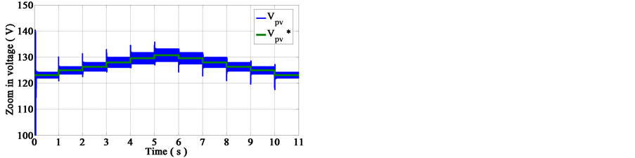
Figure 11. The output voltage of PV array based on MPPT control.

Figure 12. The output current of PV array based on MPPT control.
from Figure 11 that the relevant measured voltage signal is closely regulated; it reaches its expected reference through the action of the voltage control loop. Furthermore, the system response curves, as can be seen, exhibit minimum degree of overshoot, undershoot and steady state error.
It is also worthwhile to show the power-voltage (P-V) and the current-voltage (I-V) characteristic responses to better understand the behavior of the PV array when controlled by the proposed MPPT control technique. Figure 13 exhibits those characteristics. Under the irradiation conditions considered, six peaks have been observed at 486.3 W, 592.4 W, 702.9 W, 817.7 W, 936.9 W and 1060 W.
In the same way, the next test to carry out is the verification of the proposed MPPT control method when the system is associated to a dynamic load, changing with time as in real cases, e.g. when a photovoltaic system is connected to a grid, simulated in Figure 14(a). During this test, we also consider a solar irradiation that increases from 650 W/m2 to 750 W/m2 as shown in Figure 14(b), whereas, the temperature is maintained at a fixed value equal to 25˚C. We report in Figures 15-17 the response curve of the PV array to the variation of the resistive load, in practice this variation is observed, for example when a photovoltaic system injects active power to the utility network in case of grid connected photovoltaic system.
These curves, Figures 15-17, show that the MPPT control method tends directly towards the MPP, the operating point always follows the maximum power point very fast and does not depend on the load variations. It depends only of the input factors linked to illumination. We note also that the PV voltage is stable due to action of the MPPT driver.
As shown above, the maximum power point is achieved even at presence of load variation, to better understand the behavior of the PV system at MPPT; Figure 18 shows the P-V and the I-V characteristics of the PV array.
Finally, the performance of the MPPT control technique can be detected according to the efficiency. Table 3 summarizes some simulated results of the proposed system under different irradiation conditions; the temperature is still set to the value 25˚C. The tracking efficiency hPV is defined as [5] -[9] [14] :
 (20)
(20)
where  is the averaged output power obtained under steady state operation with MPPT and
  is the maximum available power of the PV array under certain irradiation conditions at true MPPT.


Figure 13. P-V and I-V characteristics with the proposed MPPT control method under irradiation changes.
 (a)
(a) (b)
(b)
Figure 14. (a) Simulation of the resistive load variation according to time; (b) Irradiation profile.
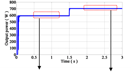

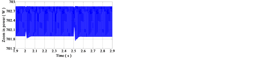
Figure 15. Influence of the load behavior on power.


Figure 16. Influence of the load behavior on voltage.

Figure 17. Influence of the load behavior on current.


Figure 18. P-V and I-V characteristics with the proposed MPPT control method under load and irradiation variations.
Table 3. Tracking efficiency of the proposed system.
From Table 3, we can deduce that the overall tracking efficiency of the proposed MPPT system is greater than 99.63% for both high and low irradiation conditions, hence the effectiveness of the proposed MPPT control method is highly ensured as required.
6. Conclusions and Perspective
In this paper, an intelligent method to track the maximum power point under rapid changes of climatic conditions was developed and tested. A Matlab/Simulink based simulation of a stand-alone photovoltaic system with a dc load stage was carried out to validate the proposed MPPT method. The results demonstrate that the proposed MPPT method track very fast the MPP with negligible oscillations. It has been also observed that the performance of the proposed method is not influenced by the load variations. A slight variation is observed when the load varies, but after a very small amount of time the system moves smoothly to the MPP. The main advantages of the developed MPPT control method are fast convergence to the MPP, high efficiency, robustness and its possibility to implement easily. Further work is being conducted on the overall system design and experimental implementation.