Electrical Shorting between the Carbon-Fiber Cloth Electrodes of Structural Capacitors with a Glass-Fiber Cloth Separator ()
1. Introduction
Multifunctional composites that have the ability to store or generate energy have recently been developed and have attracted a great deal of attention [1] . One type of multifunctional composite is a structural capacitor that uses carbon fiber fabric as electrodes. Although the total energy storage of a capacitor is not larger than that of a battery, a capacitor exhibits less degradation during charge-discharge cycles than a battery. As a result, structural capacitors have been investigated as an energy storage method for energy regeneration systems such as automobiles. For a small, lightweight vehicle, it is cumbersome to load a capacitor in the limited space available, so a structural capacitor is an attractive solution to save space. Structural capacitors have therefore recently been developed by several research groups [2] -[7] .
In a structural capacitor using carbon-fiber cloth as electrodes, the electrodes need to electrically be separated by a separator such as a sheet of paper, film or glass-fiber cloth [2] -[7] . However, using a film or paper as a separator reduces long-term reliability because it is difficult to achieve perfect bonding between the film and electrodes. Therefore, for large-scale structures, glass-fiber cloth is an attractive practical option to separate electrodes. Using glass-fiber cloth as a separator means the minimum distance between the electrodes is larger than the thickness of the cloth, so the electric capacitance is not sufficiently large in a parallel-plate capacitor. The electric capacitance can be improved when an electrical double layer capacitor is employed [6] [7] .
A structural capacitor with a glass-fiber fabric separator is easy to fabricate. However, sometimes the carbon-fiber cloth will electrically short even when glass-fiber cloth is used as a separator. In the present study, electrical shorting is considered first. A mechanism of electrical shorting is proposed, and an improved fabrication process is suggested to prevent electrical shorting between the carbon-cloth electrodes. In the present study, a parallel-plate type capacitor is used to simplify the problem of electrical shorting between carbon-fiber fabric electrodes.
2. Electrical Shorting between Carbon-Fiber Plies with a Glass-Fiber Separator
Figure 1 shows the fabrication process of the carbon-fiber fabric structural capacitor used in the present study. Carbon-fiber prepreg sheets (W3101-A/Q112J, Toho Tenux Co., Tokyo, Japan, thickness = 0.198 mm) were used as electrodes. A glass-fiber cloth sheet (E01Z SK#1017, Unitika Ltd., Tokyo, Japan, thickness = 0.013 mm) was attached with epoxy adhesive (NB102, Newport, thickness = 0.052 mm) to the electrodes as a separator to produce a sample with a length of 40 mm and width of 20 mm, which was then cured at 135˚C for 1.5 h under atmospheric pressure in a vacuum bag. Silicone rubber blocks with a thickness of 0.5 mm were used to prevent excessive epoxy resin flow. Six samples were fabricated; a photograph of a typical sample is shown in Figure 2. The electrical impedance of each sample was measured using an LCR meter (3532-50, Hioki Co. Ltd., Tokyo, Japan). To measure electric impedance with small contact resistance, copper foil was attached to the surface of

Figure 1. Schematic representation of fabrication process of a structural capacitor specimen.
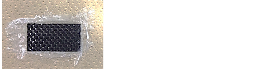
Figure 2. Typical example of structural capacitor specimen.
the polished sample. An alternating voltage of 5 V at 100 kHz was used for the measurements. The phase angle of the impedance was measured to determine electrical shorting. When the phase angle was near –90˚, the sample was judged to have capacitance. When the phase angle was almost 0˚, the sample exhibited electrical shorting because of a lack of electrical capacitance.
The impedance of the six samples was measured; only three samples showed capacitance, with an average magnitude of 200 pF. The other samples exhibited electrical shorting between the carbon-fiber cloth electrodes. This implies that glass-fiber cloth separators are not reliable for use in structural capacitors, so their reliability needs to be improved to fabricate large-scale structural capacitors.
3. Mechanism of Electrical Shorting between Carbon-Fiber Plies
3.1. Visualization of Electrical Shorting Area
We examined the mechanism of electrical shorting between the carbon-fiber cloth electrodes to improve the reliability of fabricating structural capacitors. In this section, we first visualize the area of electrical shorting using a de-ply technique and cross-sectional observation. Samples used for visualization possessed the same configuration as that shown in Figure 1. Copper foil was attached to the edge of the sample as illustrated in Figure 3. The samples were observed from the top using infrared thermography (Wuhan Guide Infrared Technology Co., Ltd., China, ±2˚C).
When a large electric current is applied to a sample with an electrical short, resistive heating causes the temperature of the sample to increase. A stable direct current generator (PW18-1.3 AT, Kenwood, Japan) was used to apply an electrical current of 0.05 A. When electrical shorting occurs in small areas, these locations can be identified from the high temperature spots observed by infrared thermography. The spots were marked using correction fluid.
After identification of the areas where electrical shorting occurred, one of the samples was divided into plies using a de-ply technique: epoxy resin was burned off using a handy gas burner and each ply was separated from the laminate. Each ply was carefully observed to investigate fiber breakage or fractionation of carbon fibers using a video microscope and scanning electron microscope (SEM). A cross-sectional view of the high-temperature area of the other sample was obtained by SEM to investigate the appearance of glass-fiber separator.
3.2. Results and Discussion
Figure 4 shows a typical image of a sample taken using infrared thermography. The temperature of the sample surface is not uniform; there are high-temperature areas. The existence of such areas indicates that the electrical shorting between the carbon-fiber electrode plies is not uniform. If electrical shorting occurs because of electrically conductive particles such as fragments of fibers or graphite crystals, the electrical short should be almost uniform because these fragments may exist almost everywhere if the fragments are the source of shorting. Moreover, the electrical contact formed by these fragments has high electrical resistance [8] . This indicates that electrical shorting in these samples is not caused by electrically conductive particles.
After marking the electrical short areas, the sample was heated to remove the resin and the three plies were separated, as shown in Figure 5 observed using a video microscope. Figure 6 shows the surface of the each ply around the electrical short area. No fiber breakage was observed. Figure 7 shows the surface of a ply where

Figure 3. Experimental procedure to identify the electrical short spots between electrodes of a structural capacitor using an infrared thermography.

Figure 4. Typical example of specimen surface image using an infrared thermography.

Figure 5. Separated plies using a de-ply technique. White dots indicate the electrical short spots identified using an infrared thermography.

Figure 7. Typical carbon fiber at the point where electrical short was not observed.
electrical shorting was not observed. Comparison of these images reveals that the surface fibers appear identical. Figure 8 presented the magnified surface of a ply in an electrical short area. There is no fragmentation of carbon fibers or graphite particles on the surface of the ply. These results indicate that the electrical shorting is not caused by carbon fiber breakage of graphite particles.
Figure 9 depicts the temperature distribution of a different sample surface measured by infrared thermography. Because the high-temperature area on the left appears at the edge where the copper foil electrode is attached, cross-sectional views of only the three middle spots were obtained. The sample was cut along the dashed line indicated in this figure. Figure 10 shows a typical cross-sectional view in a region without high-temperature areas. Here, the glass-fiber cloth acts perfectly as a separator between the upper and lower carbon-fiber cloth electrodes. A cross-sectional view of a high-temperature area is presented in Figure 11. As indicated by a circle, the carbon-fiber cloth is partially disordered and the upper layer is in physical contact with the lower. This contact point allows electrical contact between the upper and lower carbon-fiber cloth layers, creating an electrical short.
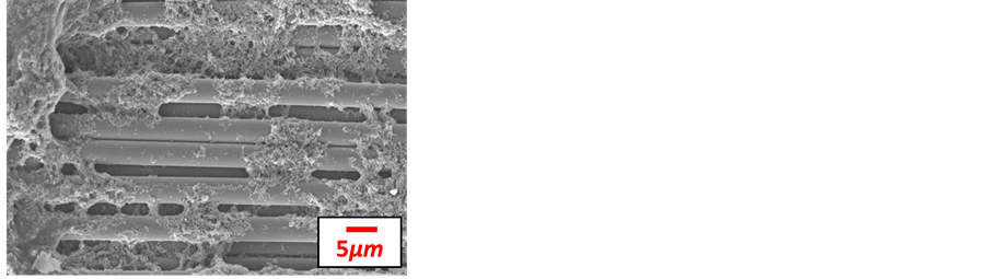
Figure 8. Magnified carbon fibers using a scanning electron microscope at the point A where electrical short was observed.

Figure 9. Result of an infrared thermography. As a copper foil electrode is attached at the left side, the broken line is used to observe the cross sectional view.
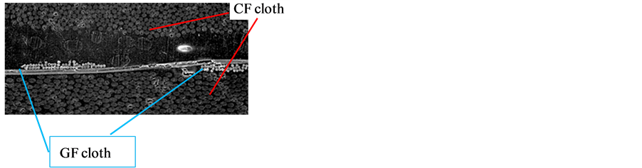
Figure 10. Cross sectional view at the point where the electrical short is not observed.
4. Pre-Curing to Prevent Electrical Shorting
In the previous section, electrical shorting between the carbon-fiber electrode cloth plies was shown to be caused by movement of the glass-fiber cloth separator during curing. In the present section, a method to prevent this movement of the fibers in the separator is proposed and experimentally investigated. To prevent fiber movement during the curing process, we pre-cured the glass-fiber cloth prepreg to prevent epoxy resin flow in it. This prevents the movement of glass fibers so that electrical shorting can be avoided. However, perfectly cured prepreg induces limited bonding between the carbon-fiber cloths. Therefore, a suitable pre-curing level is investigated experimentally.
Separators made from glass-fiber cloth and epoxy adhesive were partially cured. First, the degree of curing was measured by differential scanning calorimetry. The curing temperature and time were varied as shown in Table 1 to give three degrees of curing: 0.15, 0.68 and 0.76. The degree of curing is defined as the fraction of heat generation divided by the total heat generation of the perfect cure for each set of curing conditions shown in Table1
After pre-curing of each separator, it was sandwiched between carbon-fiber cloth prepreg layers, and then co-cured under the curing conditions described in Section 2. After co-curing of the samples, an alternating electric current was applied and the impedance phase angle was measured as described in Section 2 to investigate sample capacitance. For curing degrees of 0.15 and 0.76, three samples of each type were made. For a curing degree of 0.68, six samples were fabricated. Figure 12 shows the number of samples exhibiting capacitance. For the lowest degree of curing, all of the carbon-fiber electrodes exhibited electrical shorting. For the samples with a curing degree of 0.68, four samples out of six exhibited capacitance. All of the samples with a curing degree of 0.76 had capacitance. These results suggest that a pre-curing degree of 0.76 allows reliable fabrication of structural capacitors.
Figure 13(a) and Figure 13(b) show samples that exhibited an electrical short between carbon-fiber electrodes and electrical capacitance, respectively. Comparison of these images reveals that the sample with an electrical short has a warped surface, so epoxy resin flow occurred in it. This resin flow causes the fibers to move, allowing an electrical contact to form between the carbon-fiber cloth electrodes. To prevent electrical shorting between the electrodes of a structural capacitor, pre-curing of the glass-fiber cloth separator is required.
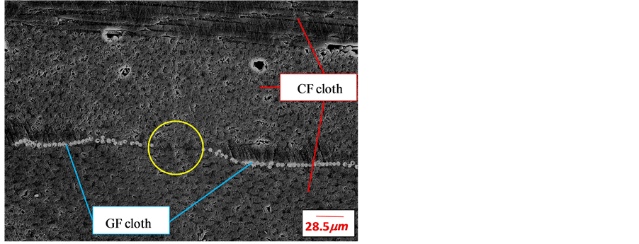
Figure 11. Cross sectional view at the point where the electrical short is observed. The point where the circle is placed has fiber contact between the carbon fiber plies.

Figure 12. Effect of pre-cure of separator fabric glass cloth ply.
 (a)
(a) (b)
(b)
Figure 13. Typical specimen configuration after curing (degree of cure of 0.68). (a) Specimen with electrical short; (b) Specimen with capacitance.
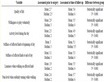
Table 1. Three types of cure conditions.
5. Conclusion
Electrical shorting between the carbon-fiber electrodes of a structural capacitor containing glass cloth as a separator was investigated. Electrical shorting between electrodes often happens in such systems because the glass fiber of the separator move through epoxy resin flow during curing. Movement of glass fibers can form a hole to allow contact between the carbon-fiber cloth electrodes, resulting in electrical shorting. Pre-curing of the glassfiber cloth separator to a suitable degree ensures perfect electrical insulation between electrodes, preventing electrical short formation.
NOTES
*Electrical shorting of structural capacitor.