Using Extended Finite Element Method for Computation of the Stress Intensity Factor, Crack Growth Simulation and Predicting Fatigue Crack Growth in a Slant-Cracked Plate of 6061-T651 Aluminum ()
Keywords:Stress Intensity Factors; Extended Finite Element Method; Finite Element Method; Slant-Cracked Plate; Crack Propagation Angle; Fatigue Crack Growth
1. Introduction
Fracture and failure are common problems with industry equipment. In modern materials science, fracture mechanics is an important tool in improving the mechanical performance of mechanical components. The stress intensity factor (SIF) is an important parameter for estimating the life of the cracked structure. In reality the stress intensity factor is a complicated function of applied loading, boundary conditions, crack growth, geometry, and material properties. By using the SIF and Paris law, the fatigue crack growth at the plate is measured. In fact, the Paris model describes the rate of crack growth in terms of material properties and the stress intensity factor. The stress intensity factor is performed using theoretical or numerical techniques. There are several numerical methods for calculating SIF like displacement extrapolation method, jintegral technique and extended finite element method [1].
The extended finite element method [2-5] can approximate the discontinuous displacement field near cracks independently of the finite element mesh through the use of interpolation functions, which can describe the displacement field near cracks in the structure. Therefore, crack modelling for stress analyses in the field of fracture mechanics can be performed more easily by XFEM than by conventional FEM. Since information about the crack geometry is required in order to determine the interpolation functions in XFEM, the level set method, which expresses the geometry implicitly as the zero contour of the level set function, can be used to simplify the computation process in XFEM analysis. Since XFEM can model cracks of structures independently of the finite element models, the number of laborious and time consuming mesh division processes can be reduced. Therefore, XFEM can be used to perform crack propagation analyses, which is not possible in practice by the conventional FEM, which often requires remeshing procedures [5-7]. Thus, using extended finite element method to simulate fracture behaviours of structures can shorten the time to estimate safety of engineering structures and reduce experiment costs. Many researchers study the extended finite element method to simulate fracture behaviour. Modelling quasi-static crack growth in 2-D problems for isotropic and biomaterial media using XFEM is described in Sukumar and Prevost [8] in which the implementation of the crack growth using the XFEM within a general purpose finite element code is also described. The numerical applications are performed in Sukumar et al [9]. A 2-D numerical model of micro structural effects and quasistatic crack propagation in brittle materials using XFEM is presented in Sukumar et al [10]. The modelling of cracks with multiple branches, multiple holes and cracks emanating from holes is presented in Daux et al [11]. The implementation is based on using the same enrichment functions for the cracks (discontinuous and tip functions) and the enrichment scheme is developed based on the interaction of the discontinuous geometric features with the mesh. Whereas for holes, new enrichment function is introduced. Modelling 3-D planar cracks by XFEM was first introduced in Sukumar et al [12], who solved several planar crack mode-I problems and showed that the method compared well with analytical solutions.
Considering the fact that no one has ever studied the comparison between the three methods of theoretical, FEM and XFEM on crack growth simulations of a slantcracked plate, in this paper using the XFEM and finite element method (FEM), values of stress intensity factor, crack propagation direction, fatigue crack growth of a slant-cracked plate were calculated by Abaqus 6.10.1 software and the results were compared with the ones from the theoretical method.
2. Extended Finite Element Method
For the purpose of fracture analysis, the enrichment Functions typically consist of the near-tip asymptotic functions that capture the singularity around the crack tip and a discontinuous function that represents the jump in displacement across the crack surfaces. The approximation for a displacement vector function with the partition of unity enrichment [13,14] is:
 (1)
(1)
where Ni(x) are the usual nodal shape functions; ui is the usual nodal displacement vector associated with the continuous part of the finite element solution; the second term is the product of the nodal enriched degree of freedom vector, ai, and the associated discontinuous jump function H(x) across the crack surfaces; and the third term is the product of the nodal enriched degree of freedom vector,  , and the associated elastic asymptotic crack-tip functions,
 . The first term on the righthand side is applicable to all the nodes in the model; the second term is valid for nodes whose shape function support is cut by the crack interior; and the third term is used only for nodes whose shape function support is cut by the crack tip [13-16].
3. FE Modeling
The 6061-T651 aluminium alloy is one of the most common aluminium alloys for heavy-duty structures requiring good corrosion resistance, truck and marine components, railroad cars, furniture, tank fittings, general structures, high pressure applications, wire products and pipelines. Many of these applications involve variable loading which makes the study of the fatigue behaviour of this aluminium alloy very relevant. The problem chosen for static analysis is slant-cracked specimen, made of 6061-T651 aluminium material [17]. The plate has dimensions of 20 × 200 and thickness of t = 6 mm with half crack length of a = 2.5 mm centered in the plate and crack angel 60 as shown in Figure 1. The plate is under uniform tensile loading acting on the upper edge resulting in magnitude stress of σ0 = 250 MPa. To compute SIF values FE and XFEM’s number of elements (NE) and number of nodes (NN) are listed in Table1 The material properties used in analysis of specimen is given in Table2
3.1. Static Analysis Results
3.1.1. Calculation of Stress Intensity Factor of the Slant-Crack Plate
As the plate dimensions are large in comparison to the crack length, thus the analytical solution given for plate for the first and second modes of stress intensity factor can be used [18]:
 (2)
(2)
 (3)
(3)
Equations (2) and (3) were used for theoretical solution. Comparison of SIF values is shown in Figures 2, 3 and Table3 All values of SIF are in MPa . Figure 2
shows the comparison between mode-I and mode-II stress intensity factor obtained numerically using XFEM, two dimensional FEM and analytical results for different crack angles with fixed crack half length a = 2.5 mm. Figure 3 shows the comparison between stress intensity factor obtained numerically using XFEM, two dimensional FEM and theoretical results for crack with inclined angle of 60 and different crack half length. Comparison of SIFs is tabulated in Table3 The results of Table 3 show XFEM KII values that are closer to theoretical values and XFEM KI values are approximately 3.55% lower than theoretical values. But the obtained results from the Table 3 show that the FEM KII values are approximately 2.8% lower than theoretical values and FEM KI values are 2.385% higher than theoretical values. As it can be realized from these results, very good agreement exists between SIFs obtained using XFEM and theoretical results confirming the robustness and accuracy of the developed XFEM formulation.

Figure 1. A schematic presentation of the plate and its loading method.
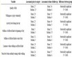
Table 1. The NN and NE for different meshes.
3.1.2. Crack Growth Simulation
Crack growth simulation consists of mainly three steps, 1) Crack initiation 2) Crack propagation and 3) Failure []">19]. All these three steps are simulated using XFEM elements in ABAQUS 6.10.1 without any re-meshing near the crack tip. The special features used in crack growth simulation are outlined below. The maximum principal stress criterion is used which can be represented as
 (4)
(4)
Where  represents the maximum allowable principal stress. The Macaulay brackets
  are used to signify that purely compressive stress state does not initiate damage. Damage is assumed to initiate when maximum principal stress ratio (4) reaches a value of unity [13,]">19].
1) Computation of crack propagation direction of the slant-Crack Plate To see the effectiveness and accuracy of the XFEM, the calculation of Crack propagation angle θcr was employed. The direction of the crack propagation θcr is established to be a function of the mixed-mode stress intensity factors at the crack tip. There are several criteria for calculating Crack propagation angle θcr like the maximum tangential stress criterion. With this criterion the fracture angle of the crack growth is defined to be perpendicular to the maximum tangential stress at the crack tip. This criterion is based on the work of Erdogan and Sih [20] and is given by:
 (5)
(5)
This is demonstrated in the Figure 4. For current investigation, initial crack is introduced at an angle of 25, 55, 60 and 80. The crack is propagated for three steps with a crack increment of 2.72 mm. Initial crack length by width ratio “a/w” was 0.125. The crack propagation direction has been simulated using XFEM in ABAQUS. For fracture criterion, Maximum principal stress as 242 MPa was used as criteria for crack initiation. Critical energy release rate as 12.367 KN/m and power coefficient as 1 were used as criteria for crack initiation with Power law. From the above Equation (5) we can see that for the cases where 0 < θ < , the fracture angle θcr is negative. Obtained results from the XFEM analysis shows good agreement with the theoretical and two dimensional FEM values which show the accuracy of the method in approximating accurately the field. The results are shown
Table 2 . Physical and mechanical properties of materials.

Figure 2. Comparison of KI and KII values for different crack Angle in the infinite plate.

Figure 3. Comparison of KI and KII values for different Crack half length.

Figure 4. Center crack propagation under uniform tension in an plate.
in the Table4
Figure 5(a) shows the plot of the theoretical solution and the numerical solutions. Figure 5(b) shows the crack propagation for all four orientation of an initial crack.
2) Fatigue Crack Growth Relating the crack growth to LEFM parameters such as the stress intensity factor makes it possible to predict the crack growth rate under cyclic loading. Thus structure life time or number of cyclic loading required for a crack to grow from its initial length up to the critical length causing catastrophic failure can be determined. Paris and Erdogan [21] proposed a law for fatigue crack growth (FCG) relating the increment in crack advanced d a to the increment in number of cycles d N and the stress intensity factor range  as:
as:
da/dN =  (6)
(6)
Where Cp and mp are material constants, determined experimentally by standard fatigue test and  is the stress intensity factor range. For mixed-mode problems, the stress intensity factor
  can be replaced by an equivalent,
  , which can be described as [22]:
 (7)
(7)
The 6061-T651 aluminium has Paris Law constant Cp of 3.7086 × 10⁻¹²  and an assumed, deterministic Paris Law exponent mp of 4.1908. Using Equations (6) and (7) and the values obtained from stress intensity factors of the above three methods, the crack length vs. number of cycles were plotted for the plate and then the results were compared. The obtained results from theoretical show that the lifetime of 5 mm, 7
Table 4 . Comparison of Crack propagation angle θcr.
 (a)
(a) (b)
(b)
Figure 5. (a) Comparison of crack propagation angle for Different initial crack configurations; (b) Center crack propagation in the infinite plate with different initial crack configurations.
mm and 8.8 mm cracks are 221, 1730 and 2500 cycles respectively. In FEM, the lifetime of 5 mm, 7 mm, and 8.8 mm cracks are 248, 1950 and 2810 cycles respectively. In XFEM, the failure values of 5 mm, 7 mm, and 8.8 mm cracks are 230, 1800 and 2600 cycles respectively. Thus, The amounts of error in FEM and XFEM are approximately 12.4 and 4 percent respectively. The results are shown in Tables 5. Also, the accuracy and validity of fatigue crack growth diagram in XFEM is closer to the theoretical method. These diagrams are presented in Figure 6 and are compared with each other. According to the overall results obtained in this paper, we can realize the capability of XFEM in the investigation of the issues such as cracks.
Table 5. Comparison of predicted Fatigue crack propagation.

Figure 6. Theoretical, 2D FEM and XFEM crack growth curves.
4. Conclusions
The main conclusions:
1) According to the SIF numerical results, XFEM KII values are closer to theoretical values and approximately 1% lower than theoretical values. XFEM KI values are approximately 3.55% lower than theoretical values. Thus very good agreement exists between SIFs obtained using XFEM and theoretical results confirming the robustness and accuracy of the developed XFEM formulation.
2) The crack propagation direction has been simulated using the XFEM in ABAQUS. Obtained results from the XFEM show good agreement with the theoretical and two dimensional FEM values which show the accuracy of the method in approximating the field.
3) The obtained results from Crack Growth Simulation show that for the cases where 0 < θ < , the fracture angle θcr is negative.
4) Efficiently using the XFEM, where no remeshing is required, each time the crack grows and there is no Need for the crack to be aligned with the elements edges in the mesh.
5) For the advantages of extended finite element method in the study of the cracks propagation, it can be said that for loading and applying the boundary conditions, exactly the same methods and conditions in the standard finite element method are applied.
6) The accuracy and validity of fatigue cracks values were much closer to the theoretical in XFEM than the FEM.
7) In calculation of stress intensity factor for crack growth analysis, the stress singularity was fixed for the crack tip in XFEM. So using the Paris equation and XFEM, it is easier and more accurate to predict the lifetime of the structures.
NOTES