Injection Scheme Optimization of Foam Profile Control on Block S103 ()
Keywords:Foam Profile Control; Numerical Simulation; Injection Pattern; Injection Cycle
1. Introduction
The technology of foam depth profile control has more than 30 years of history. Overseas, a research done by Marsden and Khan [1] concluded: Foam can slow down or even cut off the flow of high permeability zone, thus solving the problem of fluid injection displacement in the heterogeneous reservoir. The effect of CO2 foam flooding is studied by Owette [2]. Alexandrov [3] et al. studied the rule of foam filtration at porous medium. In our country, Li Zhengquan [4] verified that the foam based on polymer aqueous solution can improve the sweep efficiency of foam flooding; Du Qingjun [5] set up multicomponent mathematical seepage model of polymer; Pei et al. [6] analyzed the influence of gas fluid ratio, slug size, viscosity of crude oil on polymer aqueous based foam displacement efficiency. Nowadays, oil fields are in high water cut or in extremely high water cut; thus, water flooding problem is more and more complicated. Stabilizing oil water control technology, such as, profile control, is more and more difficult. The traditional small radius of profile control can no longer meet the requirements of stabilizing oil water [7,8]. The situation promotes the innovation and development of technology, especially in the application of the deep profile control liquid flow and improvement of the high water cut oilfield water injection [9].
This article selects the P reservoir of block S103, which has good reservoir properties. But there are lots of faults, oil and water distributing complexly. The effective thickness of average single well is only 3.1 m, thus, after water breakthrough, water cut rises fast. Among them, the water cut of some areas where local sand body develops continuously has reached 60%; thus the difficulty of development increases: the water flooding displacement efficiency is low and the cost of production rises. In this case, by the conventional adjustment technology, the remaining oil is often difficult to dig. It is less impossible to enhance oil recovery. Using foam profile control technology, this paper proposes a reasonable injection scheme by the injection of profile control agent in order to increase the sweep volume injection and change the underground flow field. The injection of medium can influence high oil saturation area, which can help to develop crude oil, slow down production decline, control water cut rising and improve oil recovery.
2. Block S103 Numerical Simulation Research
The P oil layer is the main mining of S103 block, oilbearing area is 2.56 × 10⁶ m2, geological reserves is 99.54 × 10⁷ kg, recoverable reserves is 23.25 × 10⁷ kg, air permeability is 47.3 × 10⁻¹⁵ m2 on average, the porosity is 22.7%, crude oil density on the ground is 0.859 × 10³ kg/m3, average single well effective thickness of S103 block was 11.6 m, the number of well there is 108, of which the number of oil well is 81 and the number of water well is 27. By using Petrel and S103 block’s actual geological data, we established a phased geological modeling which based on the method of random modeling. By CMG, we also establish a numerical model and tried to match the history in order to predict further development.
On the basis of establish fracture system, we divided S103 block into 137 × 144 = 19728 non-uniform angular point grid. By combining stratigraphic dip data, geological understanding and fracture system, we establish a reasonable structure model, which edge was based on the location of three major faults, and closed boundary was determined by strike. In order to guarantee the accuracy of the prediction scheme of initial conditions, we did mining history matching first, the fitting time was August 2000 to June 2011.
After forming initialization parameter field, in combination of geological, well logging and reservoir engineering analysis data, we revised the porosity, effective thickness and other uncertain parameters, after many pretreatment check, pre-processing, iterative fitting, the initialization of the reserves calculation is accordance with geological reserves, fitting reserves was 194.55 × 10⁷ kg. As shown in Table1
Fitting to June 2012, the actual integrated moisture content was 17.56%, which the fitting of integrated moisture content was 17.98%, the error was 2.4%. The moisture content of producing fluid volume and fitting are shown in Figures 1 and 2.
3. Research of Profile Control Agent Injection Solution in P Oil Layer of Block S103
3.1. The Determination of Profile Control Well Group
There were 77 wells drilled in P oil layer in block S103, 21 of them were water wells, which the rest were oil wells. Among them, the number of wells that are high in water cut oil is 14 (see Table 2), which mainly distributed in the center of block S103.
The blocks in high water cut wells were controlled by 7 water wells, they were S103, S58-44, S60-44, S61-43,

Figure 1. Fitting curve of fluid withdrawal rate in S103 wellblock.
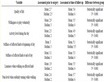
Table 1. Reserves fitting results.
Table 2. High water cut oil wells in P reservoir of block S103.

Figure 2. Fitting curve of the composite water cut in S103 wellblock.
S61-45, S63-43, S63-45. We selected S63-45, a high water cut wells, as the research object. Wells S63-45 is connected by 8 oil wells, they were S62-44, S62-45, S62-46, S63-44, S63-46, S64-44, S64-45, S64-46, as shown in Figure 3.
3.2. Reasonable Injection Pattern Optimization
There are two ways of foam profile control agent injection: gas-liquid mixing injection and gas-liquid alternating injection. We design three kinds of profile control scheme to optimizating of the above two kinds of injection way, for using the foam profile control agent formula system is: the polymer molecular weight is 8 million, polymer concentration of 1 kg/m3, the surfactant concentration is 0.25wt%, gas liquid ratio of 1:1. Profile control scheme as follows:
Solution 1: since July 1, 2012 used the method of water flooding until the water cut reaches to 98%.
Solution 2: since July 1st in 2012, the foam profile control agent was maxing injected; the injection rate was 1.273 × 10⁻⁴ m3/s, and then used the method of water flooding until the water cut reaches up to 98%.
Solution 3: since July 1st in 2012, the foam profile control agent had been alternating injected. CO2 was injected after the foaming agent solution was firstly injected with the two month injection cycle and the injection rate of 1.273 × 10⁻⁴ m3/s, and the subsequent water flooding ends until the water cut reaches up to 98%.
Three profile control schemes were studied by numerical simulation method using CMG software in well group S63-45 of reservoir P in S103 block. According to simulation results, we draw out moisture content and oil content curve which changing with time, as shown in Figures 4 and 5.
Through Figures 4 and 5, we can see that after profile control by different injection ways, after a period of time, moisture content will continue to rise, oil production will continue to fall, which means profile control measures is

Figure 3. Location map of Well group S63-45.

Figure 4. Test well group comprehensive water cut curve over time under different injection modes.

Figure 5. Oil production changing with time curve under different injection modes.
not work, then the moisture content decline, oil production rising, which shows that profile control measures work. We concluded that about nine months after the mixed way would be effective, about 3 months after the alternating injection way would be effective. Alternating injection decreases the moisture content and increases the oil content, which shows that the effect of alternating injection profile control is better than mixing injection.
Table 3 shows oil production and the change of moisture content after the profile control measures are adopted by profile control well group under the different injection ways.
We can see from the Table 3, oil wells with the highest cumulative oil production is alternating injection mode in research block, 13.750 × 10⁷ kg, 0.933 × 10⁷ kg
Table 3 . Profile control simulation results by different injection ways.
higher than to water drive, 0.167 × 10⁷ kg higher than mixed injection; during July 1, 2012 and July 1, 2015 the decline of average growing oil and average daily moisture content in profile control measures are higher than in mixed injection, which shows that alternating injection profile control effect is better than mixed injection.
3.3. Reasonable Injection Cycle
Foam profile control effect is not the same under different injection cycles. In determining the injection pattern of alternating injection, there are four design solutions for injection cycle, profile control scheme as follows:
Solution 4: foam profile control agent was injected in the form of alternating injection since July 1, 2012, the injection cycle is 2 months, the injection rate is 11 m3/d, the time profile control is 3 years, then water flooding to 98% water cut.
Solution 5: foam profile control agent was injected in the form of alternating injection since July 1, 2012, the injection cycle is 4 months, the injection rate is 1.273 × 10⁻⁴ m3/s, the time of profile control is 3 years, then water flooding to 98% water cut.
Solution 6: foam profile control agent was injected in the form of alternating injection since July 1, 2012, the injection cycle is 6 months, the injection rate is 1.273 × 10⁻⁴ m3/s, the time of profile control is 3 years, then water flooding to 98% water cut.
Solution 7: foam profile control agent was injected in the form of alternating injection since July 1, 2012, the injection cycle is 12 months, the injection rate is 1.273 × 10⁻⁴ m3/s, the time of profile control is 3 years, then water flooding to 98% water cut.
According to the results of the simulation output, we drew curves to show the change of moisture content and oil content with time (as shown in Figures 6 and 7).
We can see from Figures 6 and 7, when taking different injection cycles for profile control after a period of time, moisture content will continue to rise, and oil production continues to fall, profile control measures is not effective in this period of time, then the moisture content decreases, the oil production increases, which show that profile control measures are effective. When the injection cycle is 2 months, the result is shown earliest; however,

Figure 6. Comprehensive water cut curve of change over time of test well group under different injection cycle.

Figure 7. The curves of daily oil production over time of test well group under different injection cycles.
when injection cycle is 1 year, the result is shown latest. Thus we can conclude that the shorter the injection cycle, the more obvious of the increase of the moisture content and oil production rate.
Table 4 shows cut oil production after the profile control well group profile control measures and the change of moisture content under the different injection cycle.
We can see from the Table 4, the shorter the injection cycle, the higher cumulative oil production of oil wells in block, the average oil increases, daily average moisture content decreases under the profile control measures. The best effect of profile control can be seen when the injection cycle is 2 months, the cumulative oil production of 13.750 × 10⁷ kg, higher than to water drive by 0.933 × 10⁷ kg, and also higher than other injection cycle. That indicates that the injection cycle of foam profile control agent is 2 months in P oil layer.
Table 4. Profile control simulation results of different injection cycles.
4. Conclusion
1) According to the production characters of P reservoir of S103 block, we determine 14 high water cut oil wells and 7 water wells connected with them, and apply the profile control measures to water wells S63-45.
2) When it comes to the selection of the injection mode, the effects of alternating profile control injection work are six months earlier than the mixed injection; the cumulative oil production of alternating profile control injection is higher than mixed injection by 0.167 × 10⁷ kg; the value of the average water cut is lower than mixed injection by 6.47%. These data show that alternating injection is better than mixed injection.
3) On the injection cycle, when the injection cycle is 2 months, cumulative oil production is 13.75 × 10⁷ kg, and the water cut decreases by 10.97%. The scheme is better than others, so the reasonable injection cycle of foam profile control agent is 2 months in layer P of block S103.