Design Considerations on a Flexible Membrane Tsunami Flood Barrier ()
1. Introduction
Protection against exceptional high water floods may prevent exceptional damage to human life and goods. Recent examples of floods with massive damage are numerous. Prominent western hemisphere examples are the flooding of New Orleans by hurricane Katrina in 2005, Flooding of New York by storm Irene in 2011 and flooding of German rivers in June 2013, due to excessive rain and melting snow. The eastern hemisphere has been hit heavily by e.g the tsunami of 2004. The tsunami of 2011 in Japan caused a catastrophe at the Fukushima nuclear power plant. Sri Lanka was hit again in 2012. The Tropical Cyclone Oswald caused much damage in Australia in January 2013. Protection of endangered areas with high dikes or walls is possible. However, they represent prominent optical impressions in the landscape. Walls with add-on panels show this disadvantage to a lower extent, but their height is limited due to the high bending moment that is caused by water pressure on the wall foundation. Mobile rigid walls, hidden in the ground, or under water, intended to float upwards in case of flooding, require major investments via digging, installation and maintenance.
A membrane barrier may provide a good compromise between protection, costs and effects on local views. Membrane stresses are pure tension while bending moments are absent; this is a mechanically highly efficient construction. Moreover, foundation needs only to be designed against normal forces. Furthermore, membranes may be rolled, wrapped or folded and thus easily collapsed and stored with minimal space requirement, almost invisible when not needed. This paper presents a concept of such a membrane flood barrier and some design considerations are discussed. The membrane flood barrier is intended for self-deployment in case of flooding. So far the concept has only been presented in patent literature [1], thus in limited engineering detail only. The present paper presents more detail. Membrane forces are discussed and a design of a membrane made from ultrastrong gel-spun fibers is discussed. As an example, the required thickness is calculated, so far without safety factor, assuming a membrane with properties of a Dyneema® CF10 cloth. It turns out that a 20-meter-high flood can be contained with a CF10 cloth of about 3 mm thickness. This height of 20 meters is a flood height often mentioned for the Japan tsunami in 2011. It is arbitrarily adopted as a design case for the present paper.
The principle of the membrane flood barrier is presented in Figure 1 in a schematic way. It is a single membrane, firmly connected to a foundation on the floor


Figure 1. Sketch like presentation of a flexible membrane flood barrier, left side stored, right side deployed.
and connected to cables at the top side. The floor connection and the cables finally provide the resistance to the water pressure. An upward force is necessary at the top. This can be provided by a floating body.
2. Membrane Barrier Concept
Membrane barriers are proposed before. The so called “balgstuw” (Bellow barrier) in Ramspol in The Netherlands is a 10 meter high inflatable dike. It can be erected by filling it with air and water [2] (in Dutch language). F. van der Ziel proposed a so called Parachute barrier [3] (in Dutch language). It is not an inflatable, but a single membrane only. This parachute barrier was the inspiration for the barrier concept of the present paper. Most of the anchoring of the parachute barrier is realized with cables connected to the banks of the water way to be protected. The resulting shallow curvature may cause very high cable loads. However, it will often still be within technical limits. The barrier proposed in the present paper is only anchored to bottom foundations and kept upright by a floating body. The load carrying curved structure is smaller, curvatures are higher, thus loads are lower as will become clear later in this paper. Other differences are that the structure discussed in the present paper is mostly onshore and it may be present along kilometers length in front of the objects (cities, nuclear plants…) to be protected. The parachute barrier by van der Ziel is stored below the water surface, while the present concept comprises onshore storage above the water surface. Another concept also being similar to the presently proposed concept is the Megasecure [4], it is also a single membrane. It is “anchored” to the floor by weight and friction. The membrane shape is somewhat similar to the concept of the present paper. Megasecure is offered for flood altitudes up to 0.7 meters, whereas the limits of the present concept are much larger.
Other publications being more or less related to structural principles exploiting pure tensile stresses are the concepts of “tensegrity” by Snelson, e.g. [5], “tensairity” by Breuer [6] and the book “lightness” by Beukers [7]. In all cases, very high structural efficiency of the used materials is evident. This efficiency may also be expected for the present membrane barrier.
Figure 1 demonstrates the concept of a membrane flood barrier schematically. The barrier may be stored folded in a gutter, onshore, between the sea or river that is suspected to flooding and the objects to be protected. The bottom side of the membrane is strongly connected to a foundation. The topside is connected to a floating body (in short floater) and to mooring ropes or cables. The opposite side of the mooring cables is also connected to a strong foundation. The mooring cables may also be stored in a gutter. This situation is the left side of the scheme in Figure 1. In case of flooding, the floater will be subjected to buoyancy forces and move upward. The mooring ropes prevent displacement of the floater on flood direction. The floater lifts the membrane that stops the flood. This is the situation in the right side of Figure 1. It may be expected that some initial spilling of water over the barrier occurs if the flood rises suddenly, like in case of a tsunami, but the bulk of the flooding will be prevented.
Figure 1 already suggests some design choices to be made, the steepness of the rope and the membrane and the related buoyancy force to be provided by the floater. The next section discusses some mechanics of the deployed membrane barrier.
3. Mechanics of a Membrane Water Barrier
The static water pressure increases linearly with water depth. The local pressure p is given by the following equation:
 (1)
(1)
where p is the pressure in Pascal, g is the earth gravity acceleration, approximated by g = 9.81 m/s2, ρ is the density of the water (1000 kg/m3 for sweet water, slightly higher for sea water). And h is the distance from the water surface in meters, at the membrane location under consideration. The resultant total horizontal force per meter on the membrane Fh is thus:
 (2)
(2)
where H is the depth at the membrane foundation. Figure 2 shows the basics of Equations (1) and (2). It also indicates the mechanical situation for the membrane. The membrane is flexible, so free of bending moments. Only a tension stress is present. This tension stress and the local curvature are related according the following equation based on local equilibrium:
 (3)
(3)
where R is the local membrane radius of curvature and T is the tension force (per meter) in the membrane. The water pressure p is always perpendicular to the membrane, so the tension T is constant. Consequently, the membrane radius will increase with decreasing distance from the surface. The radius will approach infinity at the surface, so the membrane is almost straight near the water surface.
The magnitude of the membrane tension requires some additional consideration. Figure 3 shows two situations, first a membrane where the top position is exactly vertically above the position where it is connected to the foundation. This situation would be far from optimal, if even possible. However, it allows a simple determination of the upper limit of the membrane force. Moment equilibrium considerations for the upper and lower membrane points show that vertical forces do not contribute, because their working line intersect these points. Consequently, only horizontal force considerations are required for the “vertical membrane” considerations. The horizontal Force Fh working line is through the center of gravity of the triangular pressure distribution. Thus, for the bottom horizontal force on the membrane the value 2/3 Fh is present and 1/3 Fh for the top. The bottom

Figure 2. Mechanics of a vertical membrane under water pressure.

Figure 3. Forces at the bottom and top side of the membrane under water loading.
value makes equilibrium with the foundation reaction force, the top value must be provided by the ropes. The angle α at the bottom provides the membrane tension for a vertical membrane Tv:
 (4)
(4)
It was mentioned before that the vertical membrane is far from optimal. A better configuration is presented at the right-hand side of Figure 3. Considering the moment equilibrium around the top of the membrane, it is evident that the vertical foundation force contributes as well. The final effect is that overall equilibrium will be provided at a membrane tension T being lower than the value Tv. This will be treated later in the final modeling by adopting a membrane stress factor f, with f < 1. Figure 3 also indicates that the vertical component of the membrane force at the top side is much smaller than at the bottom side. That means that the required compensating floater force can be smaller as well. On the other hand, the horizontal component of the membrane tension at the top side is now larger than for the case of the “vertical membrane”. The sum of both horizontal components at top and bottom will still be equal to Fh. The horizontal component of the force at the top will make equilibrium with the horizontal component of the rope force. The vertical component of the rope force and the floater force will make equilibrium with the vertical component of the membrane force.
A designer will rather choose membrane length and rope length and choose anchoring locations and subsequently consider resultant membrane tension, rope tension and required floater force. However, from a mechanical modeling point of view, it is more convenient to start at the membrane foundation and to choose an initial membrane angle at the bottom and a certain membrane tension T being smaller than Tv, so choosing a membrane tension factor smaller than 1. Doing so, allows the creation of a rather simple iterative model. This model is discussed in the next chapter.
4. Modeling of the Membrane Shape
Modeling conveniently starts at the bottom of the membrane by choosing an initial angle α and membrane tension T, being f times Tv. The total flood height is divided in a number of steps. The first step at the bottom side is now considered. The local Radius of curvature R results from Equation 3. The horizontal membrane distance results from the vertical step size and the angle α. Subsequently the increment span length of the membrane can be calculated. The angle change over the increment is the increment span length divided by the local radius. This angle can now be superimposed to the original angle α and the first increment calculation is ready. The same calculation can be performed for subsequent increments, until the water surface is reached. All incremental steps can be administrated and total membrane span length and horizontal location is known for the initial choice. New choices can be made and calculated and various membrane configurations result. These configurations can now be judged from a practical design point of view in terms of chosen membrane span length, rope lengths and anchoring locations. Not all initial choices yield valid results. Choosing too low membrane stresses will result in downward curling of the membrane, never reaching the water surface, or to predicted sudden horizontal membrane shape differences, or error statements, all dependent on the method used for building the iterative calculation model. Such invalid configurations, based on impossible assumed membrane stress factors are easily recognized in the final result. Modeling experience indicates that about a hundred or more increments are necessary for a good calculation convergence. A thousand increments is no problem with modern calculators, so convergence is unproblematic. A very small initial angle α requires more increments. Indeed, choosing a stress factor 1 results in a membrane shape with a top position being vertically above the bottom condition. Small differences may occur due to the effect of the finite step numbers. Real analytical integration has not been attempted in view of the simplicity of the incremental method.
5. Modeling Results
The Figures 4-10 present modeling results for various membrane stress factors and values of the initial angle α. The flood altitude is rather arbitrarily chosen to be 20 meters. The water density adopted is ρ = 1000 kg/m3. The altitude of 20 meter is often mentioned in relation to the tsunami in Japan in 2011. The chosen altitude is not of importance for qualitative understanding. Yet, the calculation results will indicate that withstanding quite high floods is possible with such a membrane. It can be observed that the membrane profile increasingly tends to the flood direction (left hand direction in the figures, denoted with negative distance values) for lower membrane stress factors. Finally, slight reductions of the stress factor f cause large differences in the flood-ward extension. This might be judged at first as a very sensitive design case. However, the opposite is true. The stress factor f is not a design input. Rather the connection distances are real design inputs and the stress factor is a consequence. In fact it means that about similar stress factors result if the flood-ward extension of the membrane becomes large. It should also be noted that the lower stress factors that occur at higher values of α do not actually mean that low membrane stresses are present. It only means a low value as compared to the Tv value from Equation (4). The effect of the cosine of α in the

Figure 4. Membrane profiles for a bottom angle of 0.2 rad and various membrane stress factors f.
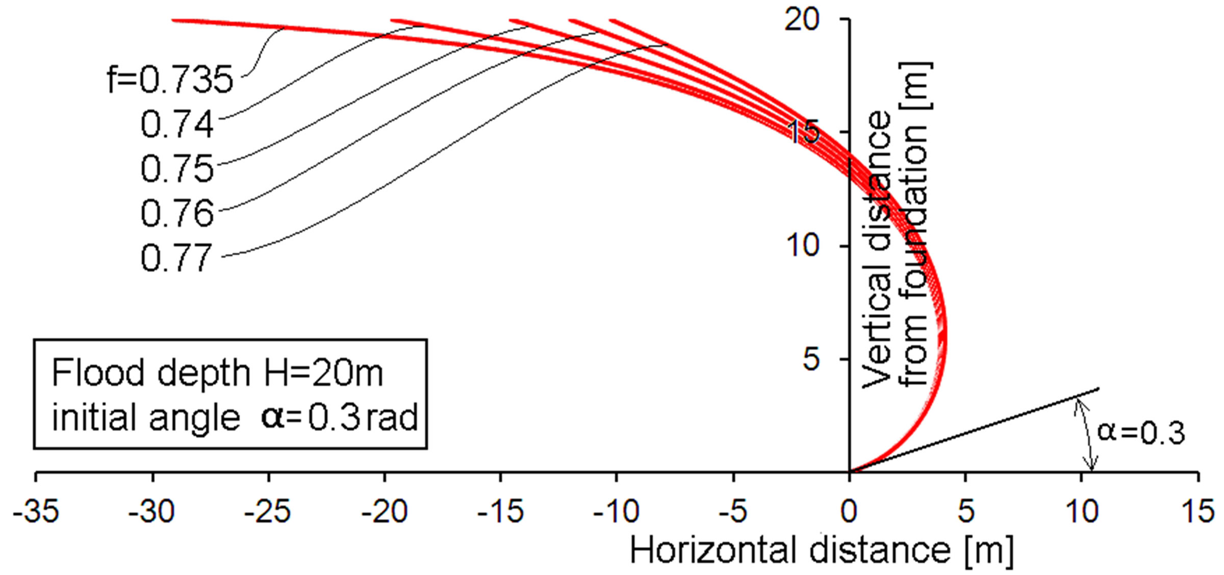
Figure 5. Membrane profiles for a bottom angle of 0.3 rad and various membrane stress factors f.

Figure 6. Membrane profiles for a bottom angle of 0.4 rad and various membrane stress factors f.
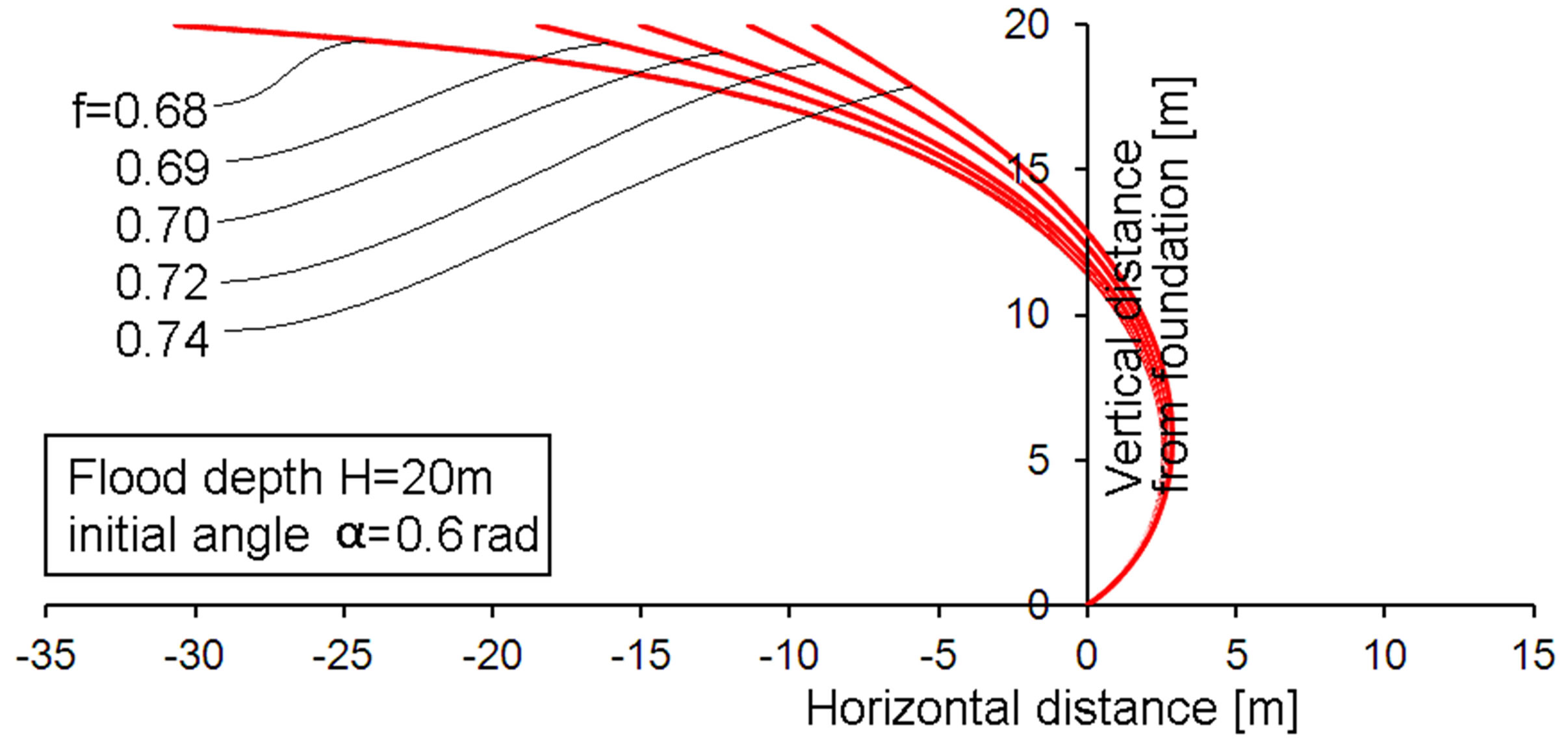
Figure 7. Membrane profiles for a bottom angle of 0.6 rad and various membrane stress factors f.

Figure 8. Membrane profiles for a bottom angle of 0.9 rad and various membrane stress factors f.
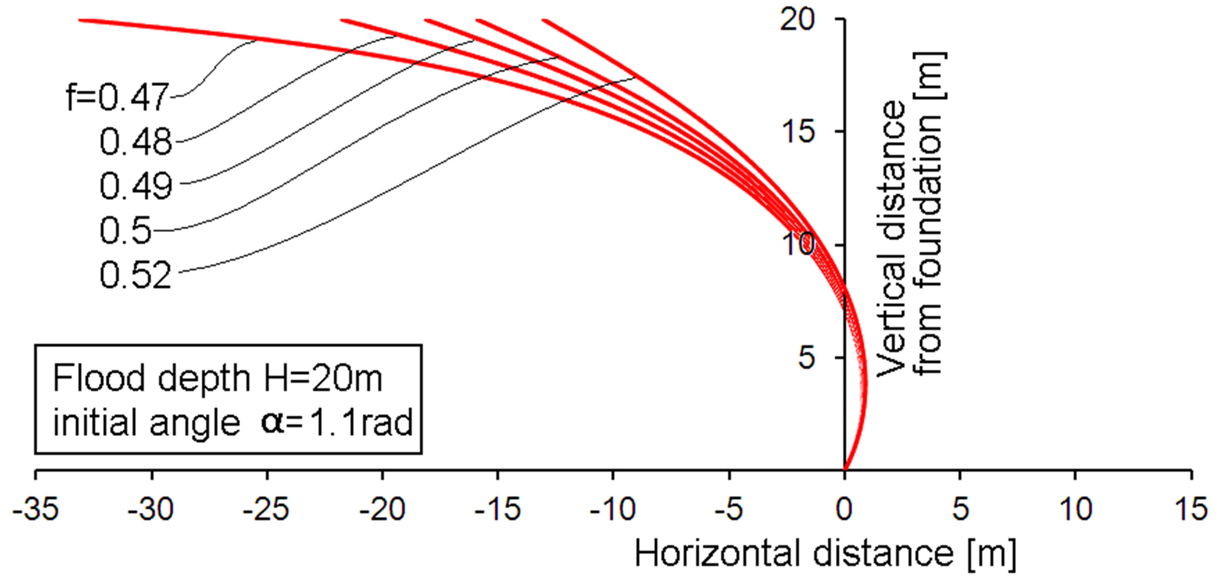
Figure 9. Membrane profiles for a bottom angle of 1.1 rad and various membrane stress factors f.
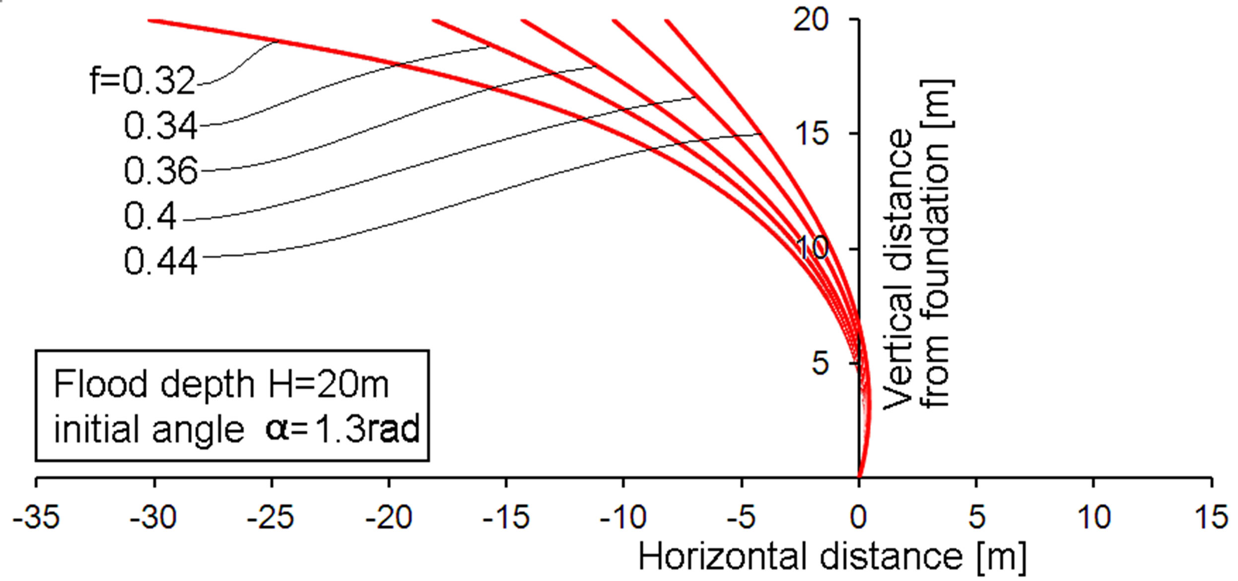
Figure 10. Membrane profiles for a bottom angle of 1.3 rad and various membrane stress factors f.
denominator of Equation (4) actually may cause a considerable increase of Tv. So the low stress factor at higher α and the effect of the cosine of α in the denominator may cancel to some extent. Actual membrane stresses are discussed later.
The Figures 4-10 present the membrane contours. However, some important engineering parameters are not visible in those figures. Such parameters are presented in Table 1 for just the same cases as presented in the figures. For the readers comfort, the bottom angle α is denoted in the Figures 4 and 5. It is omitted in the other figures. Table 1 presents the actual membrane tensile force T per meter, the membrane contour distance from top to bottom, the required horizontal component of the cable force (per meter) and the membrane related required minimum floater force. This is the vertical component of the membrane force at the surface. This last number is not the totally required floater force, because the vertical force component by the cable is not included. This choice was made, because it is dependent on the angle to be chosen for the cable. This angle is a rather simple design choice and the calculation of the cable related required floating force is also simple, and therefore not discussed much further. Only if the cables were

Table 1. Characteristic engineering data for various design possibilities for a membrane protecting against a 20 meter high flood.
horizontal, the total required floating force is equal to the membrane related floater force. For many designs, the cable related floater force would be a few times larger than the membrane related floater force. The membrane contour length is related to the amount of material needed, so to costs. The same applies to the membrane tension force. Both relations are linear, so membrane costs will be related to the product of tension force and contour length. This product is denoted as “Membrane cost parameter”.
6. Discussion
The values in Table 1 indicate the following trends:
• The membrane tension force shows little variation for the low region of initial angle α, the force increases slightly with increasing α and of course with increaseing stress factor f. However, from a conceptual design point of view, the increase is hardly relevant for values α < 0.4. The tension force increases more for larger values of α.
• A similar initially weak trend is present for the horizontal force component at the top of the barrier if α is increased.
• The vertical force component of the membrane tension force is highly dependent on the chosen stress factor f. The vertical component strongly increases with increasing f. This can be understood from the Figures 4-10, showing that the membrane approaches a horizontal orientation at the top for the smaller f-values. This will cause consequences for the required floater size.
• The vertical force component at the top also increases for increasing values of α.
• The low α-region, and especially the low f-region is characterized by low membrane tension force and large contour length. To some extend this cancels in the membrane cost factor. However not to the full extend. The cost factor is favorable for low α-values. However, low f-values make it larger, due to the large contour length.
The above mentioned trends indicate that low values of α are favorable anyhow. This region is associated with the lowest membrane costs and the smallest required floater size. So further discussion is devoted to the low α-region only.
The choice of the most attractive values of the value f is less simple. The low values of f are related to larger membrane contour lengths, so to higher membrane costs. The membrane cost factor at the lowest f-values is about 1.5 times that at the higher f-values. On the other hand, the vertical force component at the top is also highly dependent on f. especially in the lower region. So accepting somewhat higher membrane costs will result in considerably smaller floaters. For α = 0.2, the studied f-values show a range of about a factor 6 regarding the vertical force component. This factor may be more important than the factor 1.5 on the membrane costs. However, final judgment requires considering the consequences of the vertical force component and the required floater size in more detail. The upper line in Table 1 (α = 0.2; f = 0.745) is chosen as an example. The required membrane related floater force is 72 kN/meter for this situation. Assume a cylindrical floater (cylinder axis along the top of the membrane) with a diameter of 3 meter. The volume is than 32 π/4 m3 per meter length. Assuming that the cylinder is filled with a foam with negligible density and being completely submerged, the floating force will be g ρ π 9/4 = 9.81*1000*9*3.142/4 = 69 kN. So it is still not completely equal to the required 72kN. This is in spite of the diameter of the floater being already about 1/7th the flood height. Consequently, the reduction of vertical force and the related floater size will be more important than the moderate increase of the membrane cost factor. Obviously Buoyancy is an important design parameter.
Summarizing, considerations towards an optimal design lead to: Low values of α and f, resulting in a rather large membrane contour length, extending significantly towards the flood directions. Some crude numbers for an optimum design with an acceptable floater size will thus be:
• A membrane contour length being more than twice the altitude of the flood
• A connection point (cable connection) at the top of the membrane, being in the flood direction over a distance more than 1.5 times the flood altitude.
On the other hand increasing such values much further will cause extensive use of area along the places to be protected. Storage during non-flooding times may require too much space. So an optimum configuration will rather look like the most left-hand side contour in Figure 4.
So far, the discussions are on an elementary design of the membrane barrier. Especially if high floods are to be expected, more complex designs may be attractive. The required upward force at the membrane top must not necessarily be provided by buoyancy only. A configuretion with poles as compression members as depicted in Figure 11 can also provide the required upward force, now without the need for storing large floater volumes. The design in Figure 11 is now closer to the Snelson tensegrity concept containing compression poles as well. However, very large compression forces will be present in the poles. Preventing Euler buckling will require poles with a large diameter and wall thickness. Another possible variation is the application of more cables, not just only to the membrane top. Figure 12 shows an example with two cables. The lower cable takes care of a considerable portion of the horizontal load and due to the small inclination, a low downward load is caused by this lower cable. Thus a floater can be smaller. Moreover, the membrane curvature is higher (smaller radius), so according to Equation (3), the membrane tension force can be smaller. A further possible variant (not depicted anymore) could be that the upper and lower cable are connected by a pulley, whereas the pulley is connected to a foundation .The connection point of the lower cable and the membrane will shift backward (towards right-hand side in Figure 12) under loading, thus pulling the upper cable forward, independent of the original storing condition where similar end locations of the cables may be most practical. Of course combinations between the modifications from Figures 11 and 12 are also possible. So, numerous further optimizations of the barrier are possible. Such more detailed designs require more complex calculation schemes. However, the principles are the same as demonstrated above.
It is advantageous if a membrane can be made of a thin cloth. This makes storage easier. Carrying the necessary

Figure 11. Variation of a flood barrier where the upward force is provided by compression loaded poles.

Figure 12. Variation of a membrane flood barrier with double ropes.
tensile loads with small membrane thicknesses requires the use of strong materials. Reinforcement of a membrane with strong fibers is almost mandatory for high flood altitudes. The use of gel-spun UHMWPE fibers as a reinforcement is attractive. These fibers are discussed in a previous paper [8]. A fabric of such fibers, coated with a flexible polyethylene grade is e.g. commercially available by Mehler, they refer to it as Valmex. Some properties are presented in Table 2 for the most readily available thickness of 0.75 mm. The tensile strength per meter from Table 2 can be compared with the membrane tensile force in the top line of Table 1. This yields about a factor 4. Thus 4 times the thickness of the present Dyneema® laminate material would be sufficient. So about 3 mm thickness of CF10 like cloth would be needed for stopping a 20 meter high flood. So far this thickness is without adding a safety factor. Such gel-spun UHMWPE fibers are very damage tolerant as explained in [7]. So a safety factor can be moderate. Since the membrane stress is proportional to the second order of the flood altitude, the factor 4 would not be needed for a flood altitude of 10 meter. In other words; a coated fabric from Dyneema® fibers could stop a 10 meter flood (still without safety factor), with a coated fabric thickness of 0.75 mm only! This result can be compared to the values of the membrane used in the Ramspol bellow dike [2], being designed for 10 meter flood. The Ramspol membrane has a thickness of 16 mm (20 times thicker). The attractive difference with the present solution may be explained by:
1. The membrane shape of the present solution is more efficient.

Table 2. Some properties of a Dyneema® coated fabric cloth, proposed for large membrane flood barriers.
2. The Ramspol membrane contains polyamide fibers coated with rubber. The gel-spun UHMWPE fibers proposed for the present solution are about 4 times stronger than polyamide fibers.
3. The Ramspol membrane contains much lower fiber content than the Dyneema® coated fabric membrane. The fibers are the load carrying component, so the Ramspol membrane may be thicker than absolutely necessary due to a large rubber coating thickness.
4. Of course a safety factor is included in the design of the Ramspol membrane.
An extensive discussion on safety factors is beyond the scope of the present paper. Only some remarks are presented.
• The flood barriers are only loaded during limited time, so a safety factor does not have to cover the effects of “decennia loading”. Most of the time the barriers are stored in unloaded condition
• The proposed coated fabric cloth is reinforced with extremely damage tolerant fibers [8], therefore it is tear resistant and damage tolerant and local damage due to debris perforation will hardly tend to propagate.
• Consequently a required safety factor may be moderate. However, determining a realistic value requires information on the size of possible accidental damage to membranes, e.g. due to debris and it requires experimental information on the effect of such damage on the membrane tension strength.
Dynamic effects of an incoming tsunami are also beyond the scope of the present paper. However, some speculations can be made: The barrier is flexible, so an abrupt stop of all moving water will not occur, so dynamic forces may not be excessive. Moreover, temporary high water pressures will be related to high water rise and temporary over flooding of the barrier, thus limiting the loading. Detailed data will require experimental investigation, e.g. as described by Hofland et al. [9] or advanced computational fluid dynamics modeling.
So far, the discussion was based on a two dimensional view. The real barrier is a three dimensional situation. Especially the fact that the cables introduce their loads locally along the barrier will also cause a curvature along the barrier (perpendicular to the picture plane in Figures 4-12). Again this makes calculation and design more complex, however not essentially different. Treatment of the 3-D situation will require more computer power, e.g. the use of finite element calculations. The results will be dependent on a lot of design detail choices. This is beyond the scope of the present paper. The same applies to the ends of the barrier, detailed engineering will be necessary for connecting it to high coastal elements, or designing it with an inward onshore contour to higher ground with a simultaneous decrease of membrane height. All such engineering details can be solved, but are beyond the scope of the present paper.
7. Conclusion
A concept of a collapsible self-deploying membrane flood barrier was proposed. 2-D modeling provided first design guidelines and indicated that the structure is materially efficient. Protection against high floods can be provided with rather thin membranes, especially if the membranes are reinforced with very strong gel-spun UHMWPE fibers.
NOTES