Controlled Growth of Well-Aligned Carbon Nanotubes, Electrochemical Modification and Electrodeposition of Multiple Shapes of Gold Nanostructures ()
1. Introduction
Since carbon nanotubes (CNTs) discovery in 1991 by high-resolution transmission electron microscopy (TEM) [1], extensive interest has been shown in their physical, chemical, electrochemical, environmental and material science fields [2,3]. Applications of CNTs in the field of strong electrocatalytic response toward many important inorganic compounds or biomolecules [4,5] and (bio) chemical sensors [6] have recently been reported. Aligned CNT arrays (A-CNT), offer distinct advantages over loose and random oriented CNT powders. Well-aligned, densely arrayed but mutually separated CNTs, grown directly on a conductive substrate, are ideal to construct high-surface-area electrodes for amperometric chemical sensors and biosensors due to their regular porous structure, conductive path, and promoted electron transfer [7]. Recently, direct growth of A-CNTs on Ni based
[8] and Fe foils [9] was reported. Compared with Ni based and Fe foils, glassy carbon (GC) and Ta are much more stable in acidic solutions. Therefore, the unique advantage of the direct growth of A-CNTs on Ta is that individual nanotubes are electrically connected to the conductive acid-resisting substrates which overcome several obstacles in the applications, and to best of our knowledge, there is no report using Ta as a substrate to produce well aligned CNTs.
Well-aligned CNT arrays are produced mainly by dc plasma enhanced chemical vapor deposition (PECVD) [10]. The surfaces of the as-grown CNTs are pristine. CNT modifications are therefore essential to enable particular CNT array-based applications. Functionalized CNTs have favourable properties like biocompatibility [11], easier modification [12], and enhanced compatibility with composite matrixes [13]. Purification gets rid of the metal impurities inherent to the as-grown CNTs, thus eliminating the anticipated deleterious or poisonous effect of metal impurities on the long-term reliability of electrochemical reactions at CNT-based electrodes. Also the presence of oxygen-containing groups like carboxyl or hydroxyl groups facilitates exfoliation of CNT bundles and their solubility in polar media. Hydrophobic CNTs become more hydrophilic because of the oxidation [14]. Furthermore, obtained functionality is a base for further modification/functionalisation depending on application. Various approaches have been well-established for the modification of CNTs [15,16]. The harsh and solventintensive treatment in the most typically used wet chemical modification, as well as the natural drying process, when applied to the well aligned but free-standing CNT arrays, usually causes undesirable agglomeration/bundling of CNTs or even total collapse of aligned and laterally separated geometry [17]. Dry modification techniques can retain the alignment of CNT arrays; however, most of them are less efficient, flexible, or convenient than the wet chemical process [18]. Obviously, maintaining the desired vertical orientation would facilitate the implementation of CNT arrays as fuel cell electrodes, sensor platforms, field emitter components, and other applications. Therefore, in spite of all advantages of A-CNTs, their functionalisation remains a challenge because of the difficulty in preserving the desirable alignment. E. Shulga et al. [19] applied an acid vapour gasphase functionalisation to aligned CNTs using a reactor heated to a defined temperature which preserved the morphology of A-CNTs. However, reaction parameters must be carefully selected in this approach because a too aggressive treatment can easily lead to unwanted results and also a special reactor configuration is needed.
In this letter we have succeeded in fabrication of vertically aligned three dimensional CNT arrays on a conductive Ta substrate. Our CNTs were grown by CVD without being plasma aided. To make these aligned CNT arrays more suitable for sensor electrodes and other potential applications, we devised a simple electrochemical method to modify the CNT arrays with minimal damage or disruption to CNTs themselves and the aligned geometry. Quick removal of metal seed catalysts from the CNTs, eliminating the poisonous effect of metal impurities, in addition to introducing oxygen containing groups were achieved through electrochemical oxidation. Then a new simple oven drying step retained the vertically aligned and laterally spaced geometry of these freestanding CNT arrays after the wet processing, which eliminated the surface tension force during the evaporation of the water and avoided CNT agglomeration and collapse caused by the liquid-gas interface. Since the electrochemical purification does not cause significant CNT agglomeration and collapse of alignment on the substrate, further electrochemical modification of CNTs was performed directly thereafter to achieve functionalisation and decoration of CNT arrays. The attachment of gold nanostructures to the side walls of CNTs is of particular interest because of their unique structural features and important applications in many fields such as optical devices, catalysis, biological assay, and so on [20,21]. Previous routes to prepare metallic nanostructures of various shapes generally involve hard template [22] or softer directing agent, including organic surfactant, or polymer [23]. In the case of the hard template method, a rather tedious postsynthesis process is often required to remove the template used, wherein the nanostructures preformed may be destroyed or undesirable aggregates may occur when released from the template [24]; for the softer directing agent method, the multiple washings are required to remove the unwanted materials, but some residues are still bound on the surfaces of nanoparticles, which increase the difficulty of doing chemistry on the nanoparticle surfaces [25]. Up to now, these investigations have been mainly focused on the fabrication of global gold nanoparticles. Among the applied methods which are mostly complicated and time consuming, the electrodeposition is simple and low cost, and can provide an alternative way to control the particle size and shape. To our knowledge, there is no report using electrochemical methods describing deposition of gold nanoparticles (AuNPs) besides gold nanoflowers (AuNFs) on well aligned MWCNTs by varying electrodeposition parameters. Flower-like nanostructures that exhibit unique physical and chemical properties are among the most interesting anisotropic nanomaterials [26]. Interesting properties of special shapes of nanomaterials encourage our study of the preparation of AuNFs. Also interest has grown in developing non-toxic electrolytes for gold electrodeposition to replace the conventional incompatible cyanide-based bath for long term sustainability of gold electroplating. Therefore, in our work we report a onestep electrodeposition strategy for the controllable synthesis of less common gold nanostructures of various shapes on the aligned MWCNTs in the absence of surfactants and polymer.
2. Experimental
2.1. Chemicals and Instrumentation
The chemicals used for preparing synthesis solutions were acquired from a commercial vendor (Sigma-Aldrich). All chemicals and reagents are commercially available and of analytical grade. Freshly double-distilled water was used throughout the experiments and all solutions were prepared with double distilled water. Field emission scanning electron microscope (FESEM) (MIRA TESCAN operating at 20 kV) was used to observe the morphology of the prepared CNTs and Au nanostructures. Transmission electron microscope (TEM) measurements were performed with a Philips EM 208 FEG instrument operating at 90 kV. Samples for TEM were first ultrasonicated in methanol for 45 min to form a well-dispersed solution and then dropped onto a 3 mm Cu grid coated with a layer of holey carbon film. The grid was dried in oven before imaging. Elemental composition of CNTs electrodes before and after electrochemical oxidation was investigated by energy dispersive X-ray spectroscopy (EDS) (SAMX, France). The surface chemistry of as-grown CNTs and the electrochemically modified CNT arrays with oxygen-containing groups (functional groups) were confirmed by fourier transformed infrared (FTIR) and Raman investigations. Raman spectrum was measured on a micro-Raman spectrometer (an Almega Thermo Nicolet Dispersive Raman Spectrometer, a Nd: YLF laser emitting at 532 nm was used for excitation. Spectral resolution of the spectrometer was 4 cm−1). The FTIR spectra were obtained with a Perkin Elmer PC16 FTIR instrument using the attenuated total reflection (ATR) technique. Voltammetric and amperometric measurements for the synthesis and electrochemical studies were performed using an Autolab PGSTAT302N electrochemical analysis system supplied with a FRA 2.0 module (Netherland) in a three-electrode arrangement, including a working electrode (AuNPs/MWCNTs or MWCNTs), a platinum counter electrode and a saturated calomel (SCE) reference electrode, at room temperature (25˚C). All potentials were quoted versus the SCE reference electrode.
2.2. Synthesis of Well-Aligned MWCNTs on Ta Substrates and Electrochemical Oxidation of A-CNTs
In this work, a Ta-plate was used as a substrate. At first Ta substrate was polished until a mirror like surface was created. Then it was ultrasonically cleaned in ethanol before CNT growth. The 0.01 - 1 M ethanol solution of metal salt NiCl2∙6H2O (Aldrich, 99.99%), has been prepared in an argon (Ar)-filled glovebox. After that, Ta substrate was coated (sprayed) with a drop of metal chloride solution and dried by Ar. After drying by Ar, the substrate was sprayed with metal chloride solution for the second time to create two layers of catalyst on the Ta and then dried by Ar. MWCNTs were synthesized on small Ta plates by catalytic CVD with ethylenediamine as a precursor. The amine serves as both an etching reagent for the formation of metal nanoparticles and a carbon source for the growth of A-CNTs. The growth of the CNT films was performed in the tube reactor that was preheated to 850˚C. The Ni coated Ta plates were pretreated by N2 with a flow rate of 500 sccm for 5 - 20 min, forming the nanosized catalytic particles. After purging and preheating with N2, the ethylenediamine was introduced by bubbling N2 at a flow rate of 500 sccm through liquid ethylenediamine contained in a glass bottle. Thus the formed feeding gas contained approximately 8% ethylenediamine. The reaction times were varied from 5 to 45 min, after which the reactor was cooled down to room temperature in N2 ambient. By altering the growth time and catalyst thickness, A-CNTs with uniform size, good distribution and high density were produced. The dimensions of the MWCNTs are 20 - 100 nm in diameter and several microns in length. To electrochemically oxidize CNTs and introducing functional groups to them, the MWCNTs electrode was immersed in 0.2 M HNO3 solution and the potential was cycled between +1.00 and +2.00 V at a scan rate of 50 mV∙s−1. The effect of the electrochemical treatment was controlled by the number of the potential cycles during electrochemical oxidation. An oven drying technique (80˚C - 100˚C) retained the vertically aligned and laterally spaced geometry of these CNT arrays after the electrochemical processing.
2.3. Electrodeposition of Au Nanostructures on MWCNTs Electrodes
Electrodeposition of gold nanostructures (GNs) on CNT arrays was performed by a simple template-free method using chronoamperometry. At first, the consecutive CV over a suitable potential range of 0 to 1 V at a scan rate of 50 mV∙s−1 was investigated on MWNTs modified electrode by using electrochemical reduction of 0.5 M H2SO4 containing 5 mM HAuCl4 solution. Secondly, electrodeposition was carried out by the potential-step technique (chronoamperometry) from an acidic solution of 0.5 M H2SO4 containing 5 mM HAuCl4. The applied potential was stepped from +0.80 V where no Au is deposited on the electrode surface, to +0.20 during 10 and 20 s. The obtained MWCNTs-Au modified electrodes were washed carefully in deionized water and then dried at room temperature. Such prepared electrodes were ready for electrochemical measurement and further analysis.
3. Results and Discussion
3.1. Synthesis and Characterization of A-CNTs on Ta Substrate
Figures 1(A) and (B) shows SEM images of the well aligned CNTs on the polished Ta substrate at 850˚C after 6 min. As it can be seen well aligned CNTs can grow on the substrate with proper orientation and high density.
Regarding investigation of the different parameters on the CNTs growth and alignment, it was observed that using two layers of chloride-nickel solution on the pol-

Figure 1. (A) and (B) SEM images of well aligned CNTs grown on the polished Ta substrate at 850˚C after 6 minutes shown with different resolutions; (C) and (D) TEM images of bamboo-like structure multi-walled CNTs with different resolutions.
ished substrate (with concentration of 0.1 M), pre-heating the substrate for 4 minutes to produce the metallic nanoparticles and then allowing CNTs to grow at 850˚C after 6 minutes on the polished substrate, well aligned and high density CNTs with diameter between 20 - 100 nm and length of several micrometers were produced. Figures 1 (C) and (D) also shows TEM images of the ACNTs. In the Figure 1(C) it can be observed that CNTs have bamboo-like structures and achieved CNTs are multi-layered. Also in Figure 1(D) it can be seen that tips of the CNTs are closed. No catalyst particle can be observed on the tip of the CNTs indicating that root growth was dominant in which catalyst particles are kept stuck on to the substrate surface.
3.2. Purification of Vertically A-CNTs by Electrochemical Oxidation
From different oxidant that can be used in electrochemical oxidation, nitric acid is the most common agent for purification since it can mildly oxidize and can selectively dissolve the amorphous carbon and metallic catalysts. It is non-toxic and cheap. Electrochemical oxidation of A-CNTs was performed by using cyclic voltammetry at the potential between 1 and 2 V and scan rate of 50 mV/s in nitric acid with concentration of 0.2 M.
Then CNTs were washed with deionized water and dried in the oven with temperature of 80˚C - 100˚C to keep their alignment and orientation. This means that drying the CNTs in ambient temperature makes CNTs to be curved, clustered, severely agglomerated and damaged in term of alignment. Such agglomeration and collapse are highly undesirable as a major portion of the CNT surface is now blocked and less accessible for electrochemical reactions.
Therefore, adhesion forces should be omitted or lowered during evaporation to stop CNTs agglomeration [27]. To avoid CNT agglomeration and collapse caused by the liquid-gas interface, a simple oven drying step was introduced after the electrochemical oxidation of CNTs to eliminate the surface tension force during the evaporation of the water.
Figure 2(A) illustrates the cyclic voltammetry of the electrochemical oxidation of CNTs in the potential range of 1 - 2 V for 10 cycles. As it can be seen in this figure, the peak current remarkably subsides in each time of scanning till it reaches the minimum amount. This states that Ni catalyst is dissolved, MWCNT oxidation is efficient in high potentials and it is totally irreversible. This method alters the CNTs surface characterization from hydrophobe to hydrophyle which is so desirable for later possible modifications of the CNTs with metallic nanoparticles like gold.
Figure 2(B) shows SEM image of vertically A-CNTs grown on the Ta substrate using chloride-Ni solution with concentration of 0.25 M, after electrochemical oxidation in nitric acid. It can be observed that the alignment of the CNTs is desirably kept after this process. The relative purity of the CNTs in terms of the Ni catalyst contents has been investigated before and after electrochemical oxidation using EDS (Table 1). The amount of carbon, Ta substrate and Ni catalyst can be clearly observed and compared. As it can be seen the amount of Ni considerably decreases after oxidation which confirmed metal impurities from CNTs were dissolved in HNO3 solution. Therefore it can be inferred that oxidation process to remove metallic catalyst not only was efficient, but also alignment of the CNTs are kept.
To characterize chemical groups on CNTs surface
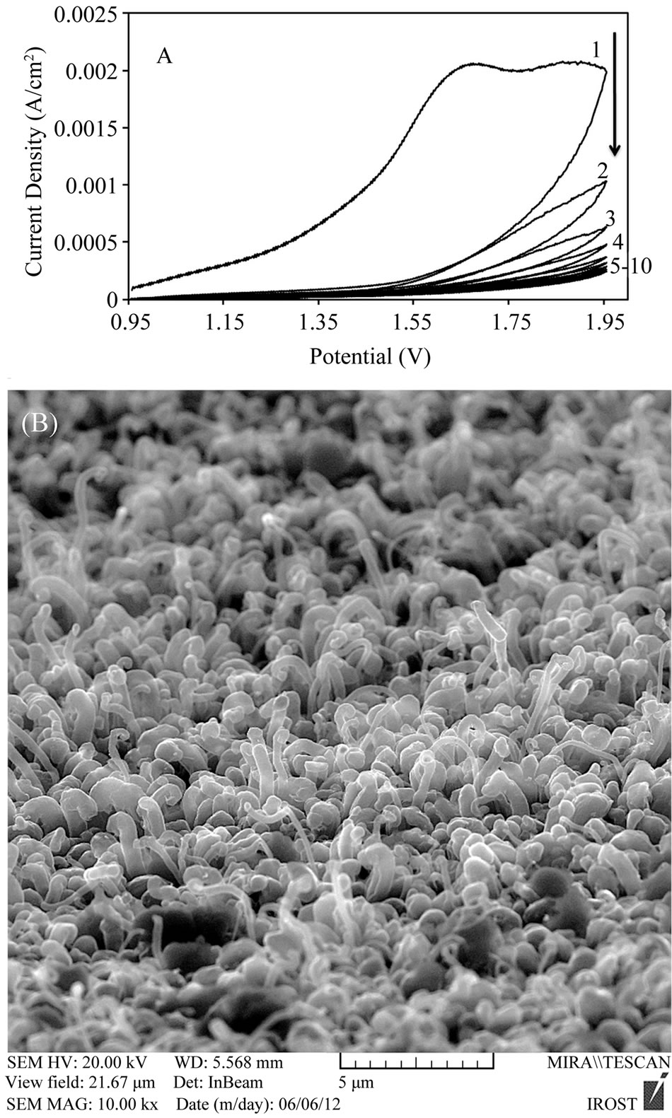
Figure 2. (A) Cyclic voltammetry diagram for CNTs electrochemical oxidation with sequential cyclic potential in nitric acid with concentration of 0.2 M and scan rate of 50 mV/s; (B) SEM image of well-aligned CNTs grown on the Ta substrate using chloride-Ni solution with concentration of 0.25 M after electrochemical oxidation in nitric acid with keeping CNTs alignment.

Table 1. The amount of different elements of the CNTs coating before and after electrochemical oxidation.
FTIR and Raman spectra of vertically aligned CNTs before and after electrochemical oxidation in nitric acid were measured and analyzed. Figures 3(A) and (B) shows FTIR spectra of CNTs before and after electrochemical oxidation in nitric acid. It can be observed that very weak peaks appear in Figure 3(A) and the spectrum of the as-prepared MWCNTs shows the C-C stretching
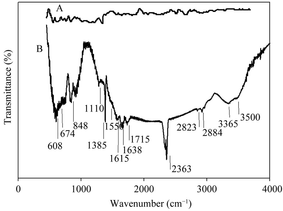
Figure 3. (A) FTIR spectrum of CNTs before and (B) after electrochemical oxidation in nitric acid.
bonds in the range of 1580 - 1650 cm−1 characteristic to the expected nanotube phonon modes. The absorption band related to C-N bond can be observed at 1110 cm−1 which indicates the appearance of amine groups upon using ethylendiamine in a N2 flow in CVD process [28]. The HNO3 oxidative treatment produces oxygen containing groups on the surface of the MWCNTs (Figure 3(B)). It can be seen that the peak in 1715 cm−1 is associated with -C=O stretching of the carboxyl group. Peaks around 3000 - 3500 cm−1 are associated with -O-H stretching bond in carboxyl and hydroxyl groups. The absorption band related to C-N bond can be observed at 1110 cm−1 which indicates the appearance of new amine functional groups upon functionalization process in HNO3. Peaks occurred in 2884 cm−1 and 2823 cm−1 are associated with C-H stretching bond in aliphatic -CH2 and CH3 groups. Deformation and bending of different types of C-H bonds are characterized by peaks below 900 cm−1 [29,30]. In facts bands in the range of 1750 - 1550 cm−1 can be associated to C=O groups, in different environments (Carboxylic acid, ketone/quinone), and to C=C in aromatic rings; while bands in the range of 1300 - 950 cm−1 proves the presence of the C-O bonds in various chemical surroundings. C=O bonds as characteristics of carboxyl functional groups (-COOH) and ketone/quinone can be observed in 1711 and 1638 cm−1 [31,32]. Observed peak around 2363 cm−1 also can be associated to ionic amines C=NH+.
Raman spectrometry is a beneficial tool in analyzing degree of graphitization of carbon-based materials. Figures 4(a) and (b) shows Raman spectra of the CNTs before and after electrochemical oxidation in nitric acid. Observed Raman band in 1584 cm−1 is attributed to the stacking of the graphite hexagon network plane (G-band) while the other band in 1347 cm−1 is related to the amorphous carbon or deformation vibrations of a hexagonal
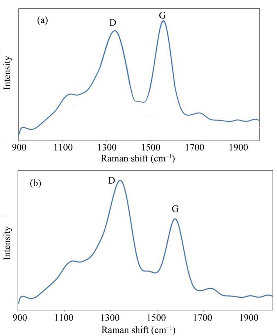
Figure 4. (a) Raman spectra of CNTs before and (b) after electrochemical oxidation in nitric acid, with different Dband and G-band modes.
ring (D-band) [33,34]. Since G-band modes depend on diameter, it is clear that G band occurred for CNTs with big diameters would be similar to that of graphite single peak G band. This similarity can be seen for MWCNTs where a single peak occurs around 1584 cm−1 which is like that of graphite. However, in SWNT, this band has two peaks which are uniquely belonged to single-walled CNTs. Therefore it can be concluded that obtained CNTs in this research are multi-walled CNTs. It is acknowledged that the ratio of the intensities of the D and G peaks (ID/IG) reveals useful information on the graphitization degree and lattice distortion of the carbon-based materials [35]. The D-band indicates, as usual for carbon nanostructures, the density of defects and can be used for monitoring the process of functionalisation which transforms sp2 to sp sites. Different ID/IG ratios of the samples illustrate different crystalline structures. As-synthesized A-CNTs have the ID/IG ratio of 0.91 before electrochemical oxidation while this ratio was equal to 1.48 for functionalized CNTs. This increase can be attributed to the electrochemical oxidation.
Furthermore a considerable shift in G mode (+14 cm−1) can be seen which is related to the changes in MWCNTs electrochemical structure due to the change in amount and type of the chemical groups attached to the walls and tips of the A-CNTs and/or amount of the increased oxygen content in CNTs structure that can acts as p-type dopant [36].
3.3. Deposition of the GNs on Well-Aligned CNTs Using Electrochemical Method
After electrochemical modification of the CNTs, purification and adding up functional groups containing oxygen; in next stage new gold nanostructures were deposited on CNTs using a simple electrochemical method namely chronoamperometry (potential-step method). Figure 5(A) represents a typical consecutive cyclic voltammetry (CV) curve for an acidic solution of 0.5 M H2SO4 containing 5 mM HAuCl4 at a scan rate of 50 mV/s. The broad band around +0.90 V represents the reduction of adsorbed  ions to Au0. The sharp peak at +0.58 V corresponds to the reduction of Au(III) to Au0 [37]. The increase in peak current with increasing number of potential cycles, informed that Au0 particles were increasingly loaded onto MWCNT. Furthermore, no anodic current is observed on the reverse sweep indicating the irreversibility of the reduction of
 . The SEM images (Figures 5(B) and (C)) also shows that Au nanostructures in shapes of cauliflower, which present rather “special”, have been successfully deposited onto the A-CNTs surface by using this consecutive cyclic voltammetry.

Figure 5. (A) Cyclic voltammetry diagram of gold nanostructures in shapes of cauliflower from acidic solution of 0.5 M H2SO4 containing 5 mM HAuCl4 with cycling of potential between +1 to 0 V and scan rate of 50 mVs−1; (B) and (C) SEM images with different resolutions of precipitated gold nanostructures by using cyclic voltammetry at the mentioned condition.
Each cauliflower-like particle is the conglomeration of numerous grains, which goes through three steps during the growth process: 1) formation of nuclei, 2) tiny particles aggregation on nuclei and 3) growth of nucleus into crystal grains.
Figure 6(A) shows chronoamperometric curve for electrochemical deposition of GNPs on the A-CNTs electrode in 0.5 M H2SO4 solution containing 5 mM HAuCl4 at a constant potential of +0.2 V and time of 10 s in which the current density increases at initial stages due to the nucleation and growth process and then drops by increasing the concentration gradient of electroactive species on the surface (i.e. growing the diffusion layer into the solution) [38] according to Cottrell Equation (1):
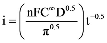 (1)
(1)
where n, F, C∞, D and t are the number of exchanged electron involved in the electrode process, Faraday constant, the solution bulk concentration, diffusion coefficient, and time respectively. The well-defined maximum peak is a result of encountering two mentioned phenomena (i.e. nucleation and growth with diffusion). Based on the linear relation of current with reverse square root of time, diffusion coefficient could be determined from the slope of the curve (the inset of Figure 6). The calculated


Figure 6. (A) Chronoamperometry curve of the deposited GNPs on the CNTs at potential of +0.2 V after 10 s in 0.5 M H2SO4 containing 5 mM HAuCl4, the inset shows the related i-t−1/2 diagram; (B) SEM image of the deposited GNPs on the CNTs using chronoamperometry at the mentioned condition; (C) SEM image of GNPs on A-CNTs at the same condition with keeping the alignment from the side view.
value for D was 2.45 × 10⁻⁷ cm2∙s−1 for a 5 mM gold solution. Considering that the potential-step method is usually used to deposit metal nanoparticles with a high surface-to-volume ratio instead of uniform metal film on an electrode, we used this method to replace the CV method. The electrode potential was stepped from an initial potential of +0.8 V, where no reaction occurred, to +0.20 V, at which potential  was reduced to Au nanocrystals. Presumably, the reduction of
  to Au0 begins at surface defect sites where oxygen-containing functional groups, such as carboxylate, serve as axial ligands.
Figure 6(B) shows SEM image of precipitated GNs on the vertically aligned CNTs using chronoamperometry at constant potential of +0.2 V. As it can be seen in Figure 6 spherical nanoparticles with small diameters and high density were well dispersed deposited on CNTs which is related to the nucleation of Au nanoparticles at the dense edge-plane-like defects on MWCNT and also it displays a three-dimensional growth of these GNPs and clusters on the active sites. In some cases GNPs completely cover the CNTs surfureces and in some points aggregate of nanoparticles can be observed considering that some particles grew more rapidly and over lapped with other particles. Also Figure 6(C) depicts the SEM images of the deposited GNPs on the A-CNTs from the side view. As it can be seen nanoparticles with appropriate density are uniformly precipitated on the A-CNTs without violating CNTs alignment. The average diameter of these GNPs ranged from 20 to 100 nm. The EDS spectra confirmed the presence of the gold peaks in the resulted coating on the Ta substrate (not shown here). The characteristic shape of the curve in Figure 6(A) confirms the occurrence of nucleation and growth processes in the system. As it can be seen for spherical nuclei, the rate of the nucleation is comparable with their growth rate and the current transient shows a maximum then subsides to the critical diffusion current on the electrode surface. An initial sharp current spike is due to the charging of the double-layer which has been eliminated here. The curve then exhibits a hump shaped response following the charging current spike which commonly observed for the electrochemical nucleation and 3-dimensional (3-D) growth of metal crystallites [39]. After the hump, a current decay is observed indicating a planar diffusion regime. This situation develops due to overlap of growing hemispherical diffusion layers which initially provide mass transport for nanocrystal growth [40]. The position of the hump in this figure within the first 1s argues that the growth of the Au nuclei is relatively rapid.
Figure 7(A) shows the chronoamperometry curve of the deposited Au nanostructures in flower-like shapes (nanoflowers and nanosheets) on the A-CNTs at potential of +0.2 V after 20 s in 0.5 M H2SO4 containing 5 mM HAuCl4 . Also, Figures 7(B) and (C) shows the SEM images of the deposited Au nanoflowers on the A-CNTs under this condition. The overall behavior of chronoamperometry curves are similar (Figures 6(A) and 7(A)), but by increasing the deposition time, growth rate dominates particle nucleation rate so nanoflowers can be formed.
As it can be seen in Figure 7(C) a mass of tanglesome particles are coexistent with some sheetlike particles. Longer reaction time seems in favor of the growth of gold nanosheets and nanoflowers and the products were mainly gold nanosheets with irregular shapes and nanoflowers and only small amounts of spherical particles were observed (Figures 7(B) and (C)). The width of the gold nanosheets is several hundreds of nanometers respectively. Actually, during a prolonged deposition time, electrodeposited nanoparticles are not formed into spheres, in some parts aggregation of particles can be seen as flower-like shapes and the nanoparticle clusters acted as the initial seed and grew into 3D nanoparticle arrays. So a longer deposition time resulted in a longer growth process so that particles have time to grow and aggregate. In principle, crystal growth and crystal morphology are governed by the degree of supersaturation, diffusion of the reaction species to the surface of the crystals, surface and interfacial energy, and structural anisotropy of the crystals. Fractal and dendritic growth are expected in the diffusion-limited regime, away from the equilibrium conditions [41]. Here, the fabrication of gold nanoflowers and flowerlike gold nanoparticle arrays may follow a diffusion-controlled growth model.
Nanoflowers are not currently reported so frequently, as nanowires or nanoparticles. These scarce and new nanostructures often emerge because of the combination of van der waals force and the anisotropic hydrophobic attraction between the nanoparticles [42]. In Figures 7(B) and (C) the individual gold nanoparticles was shown with many triangular shaped petals and changeable diameters from the base to tips. These metal petals with the sharpened tips on the widened bases were connected to one center core to form the flower-like structures.
The successful purification and the successful lesscommon Au nanostructures deposition, indicate good electrical contacts between Au electrocatalyst and CNTs, as well as those between CNTs and the substrate. Therefore, such purified CNT arrays with vertically aligned and mutually separated geometry on a conductive Ta substrate besides the flower-like Au nanostructures can provide an ideal platform for constructing electrically driven nanodevices, such as biosensors, bioactuators, battery electrodes, and so forth.
4. Conclusion
In summary, a CVD approach has been introduced to
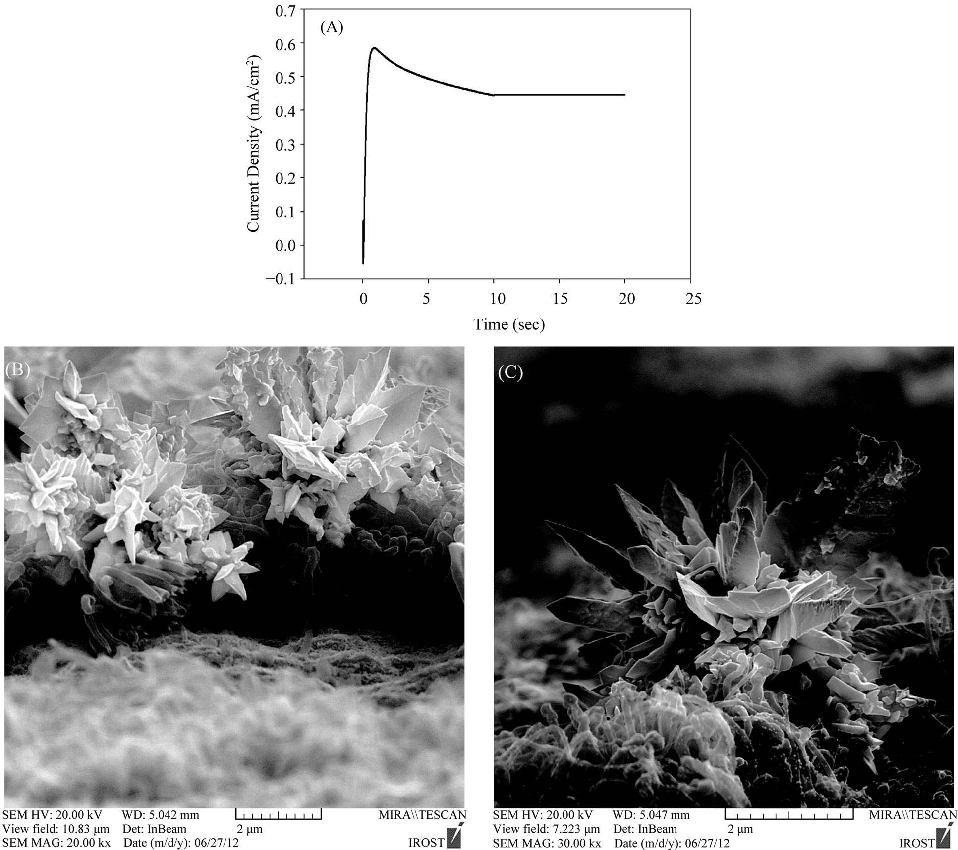
Figure 7. (A) Chronoamperometry diagram of precipitated gold nanoflowers and nanosheets on A-CNTs at potential of +0.2 V after 20 s in 0.5 M H2SO4 containing 5 mM HAuCl4; (B) and (C) SEM images of gold nanoflowers and nanosheets on ACNTs by using chronoamperometry at the mentioned condition.
produce three-dimensional free-standing MWCNT arrays vertically aligned on a conductive Ta substrate. The diameter of CNTs was in the range of 20 to 100 nm and the length can be changed in several microns by varying the CVD parameters. Simple and effective CNT functionalization and purification were achieved through electrochemical oxidation with mainly hydroxyl and carboxyl functional groups. The unidirectionally aligned and laterally spaced geometry of CNT arrays was fully retained in each step of electrochemical modification, and the oven drying process prevented undesirable bundling/agglomeration of CNTs after the electrochemical process. Various less-common gold nanostructures including flowerlike nanoparticles arrays, nanosheets and nanoflowers were then deposited onto the sidewalls of such A-CNT arrays through simple template-free electrochemical methods (chronoamperometry and cyclic voltammetry). A diffusion coefficient of 2.45 × 10⁻⁷ cm2/s was calculated for 5 mM non-toxic gold solution at +0.2 V. These scarce nanostructures of gold on A-CNTs have widespread technological potential in the design and development of next-generation fuel cells, catalysts and bio-sensors, which is underway.
NOTES