Introduction
It is written in the books that electrical energy is transmitted through the wires, but what exactly does flow inside the wire? Today there exist generally accepted descriptions of processes occurring in an electric circuit. These descriptions are based on a model in which electrons (or other charges) move inside a conductor. In some literature it is written that the electrons do not move, but push each other, as in the well-known “domino effect”.
But such an explanation is not plausible. Electrons are mechanical particles that have mass [1] . They cannot move or push each other at the speed of light. But an electrical signal is transmitted at the speed of light. If so, then how electrical energy is transmitted in a wire system? Here is a modern explanation of how electrical energy is transmitted in wires. The source creates a potential difference. The potential difference creates an electromagnetic field. This field propagates along the wire on its outer surface at the speed of light (this creates a well-known skin effect). So, wire is not a tube with a current inside. The current does not exist at all.
Does One Need Grounding? There is a common opinion that all electrical systems and all devices must have zeroing [2] [3] . This work is licensed under the Creative Commons Attribution International License (CC BY 4.0). http://creativecommons.org/licenses/by/4.0/ Open Access M. Bank DOI: 10.4236/eng.2019.1112054 802 Engineering connection with ground. But at the same time, there are contradictions in the explanations of grounding systems functioning. In these systems, the current enters the earth. But today it is known that it is impossible to find out any traces of this current at distance of a few meters. If so, where does the current go? There are many attempts to explain these processes. And all these explanations are different. Some people assume that the earth is a huge capacitor. But, firstly a capacitor should have the second plate.
And, secondly, there should be a dielectric inside a capacitor. But the earth is not a dielectric. Other explanations assume that grounding as current absorption. But absorption cannot be infinite. Any sponge, when it is filled with water, stops absorbing. There are other explanations as well, but all of them cause new questions. Let’s consider the following hypothesis. The current which is injected into a ground is divided into a great number of weak currents. When ground depth, the quantity of currents grows and therefore the amplitude of each current decreases to zero. Can current flow through broken wires? Yes, it can, for example, in a linear antenna. In the case of electrical antenna like a dipole or monopole, the current stops at the ends of radiators but its energy converts into the energy of the electromagnetic field. It means that the energy path is not interrupted.
Now we can imagine grounding or zeroing as a set of very short monopoles. It is known that monopole which height (h) is much less than a quarter of wavelength has radiation resistance close to zero. Recall that the wavelength at a frequency of 50 Hz is 6000 kilometers. This resistance tends to zero as length of antenna compared to the quarter of wavelength. Radiation resistance decrease leads to radiating power decrease. So, we can say that monopole with 5 - 10 m high at frequencies 50 or 60 Hz has zero resistance and zero radiation field density.
Note that a monopole with height much less than the quarter of wavelength has a capacitive component. However, parallel connection of monopoles results in capacitive resistance decrease. In other words, perhaps grounding is a system consisting of a considerable quantity of monopoles, with length much smaller than quarter of a wavelength.
An Unbalanced Single Wire Earth Return (SWER) System the energy is transmitted by one wire. The second source terminal and the second load terminal are connected to the ground. This unbalanced line can transmit all the energy from source Tx to load Rx. But there is one problem. Potentials of grounding in the Tx and Rx are the same (zero). However, potentials in active terminals of transmitter and in receiver are different due to a signal delay. So, Tx and Rx signals have a different potential difference. It shall be noted, that in the balanced circuit with active load, the potential difference on receiver input does not depend on signal delay, as potentials at the ends of both wires change equally by a delay.
This situation can be likened to the problems similar to reactive load influence. And in the case of long lines, this system loses a large amount of energy. It is possible to compensate reactive power, but this compensation is expensive in the case of variable loads. In contrast to the SWER system, the proposed one-wire system is a balanced system. In it, the potential difference on the load does not depend on the line length and is always equal to 180 degrees.
Now the dominant electric energy transmission system is the three-phase system proposed by the Russian scientist Dolivo-Dobrovolsky. The important advantage of this system is that a generator and an electric motor are effectively built, because in these devices, three windings are located on one rotor. But today it is already clear to many specialists, that this system has more disadvantages than advantages. Here are these disadvantages: 1) Many expensive wires (three or four); 2) Large expensive supports for wires; 3) Underground and underwater three phase system are very expensive; 4) Large number of broken wires short circuits; • Large energy losses due to phase’s imbalances and reactive power; 5) Strong negative environmental impact including Corona Effect, it’s time to free the earth (see Figure 1). In this case, one can say that three phase system is three SWER systems. As in SWER, this phenomenon is equivalent to the presence of reactive resistance in the load and, consequently, the appearance of reactive power. It is shown in [1] that reactive power value in three phase system noticeably increases if cables have linear capacitances and linear inductances. That is why there are intermediate stations sometimes every about 30 km. One-wire system allows transmitting the energy from three phase source by one wire. In this case in one wire one can use the one of three wires of equivalent three phase system [1] . For transmitting three phase signals by one wire signal it is possible using special converter [4] .
One Wire System in [5] universal balanced one wire system is proposed. All loads receive signals with phase difference 180 or 120 degrees. And this is independent of the line distance. An output single wire is divided by number of loads. Each load receives a signal with its own parameters. For this purpose, set of converters have been proposed, so that C 2-1 and C 3-1 in transmitter converts to C 1-2 and C 1-3 in receiver. It is well known that the main part of power electrical system cost is wires.
In [1] it is shown also that for one wire system can use one of the wires which are used in three phase system. A calculation shows that one wire system can be three time cheaper than three phase system (Figure 2).
![]() 1. Sine Source; 2. Inverter; 3. Nullifier; 4. Simulation of consumer in the form of resistance.
1. Sine Source; 2. Inverter; 3. Nullifier; 4. Simulation of consumer in the form of resistance.
Figure 1. Converter 2 - 1 - 2.
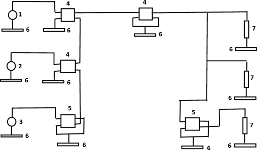
1. Sine wave source with 0 degree phase; 2. Sine wave source with 120 degree phase; 3. Sine wave source with −120 degree phase; 4. Transformer; 5. Inverter; 6. Nullifier; 7. Simulation of consumer in the form of resistance
Figure 2. Converter 3 - 1 - 3.
Now, we can move from the second part of the past to the first part of the future. Today our entire globe is covered by three-phase lines. These lines very expensive, introduce losses, heat the ground and cause power outages.
If we replace them with single-wire lines and lay them underground, then the above disadvantages will not exist.
Translation is too long to be saved.
For a long time, information sources have been discussing the possibility of obtaining an unlimited amount of energy using wave power plant (WPP). That is, power plants located in the aquatic environment, the purpose of which is to obtain electricity from the kinetic energy of the waves. The energy potential of the waves is estimated at more than 2 terawatts. As shown in Wikipedia, there are still unresolved problems for the widespread use of wave energy. For example, it is necessary not to affect fish and fishermen. The technical problems associated with the collection of electrical energy and its integration with existing systems for generating electricity on earth have not been resolved either. One of these problems is the problem of synchronizing the parameters of electrical signals in phases too long to be saved.
For a long time, information sources have been discussing the possibility of obtaining an unlimited amount of energy using wave power plant (WPP). The energy potential of the wave is estimated to exceed 2 terawatts [1] .
That is, power plants located in the aquatic environment, the purpose of which is to obtain electricity from the kinetic energy of the waves. The energy potential of the waves is estimated at more than 2 terawatts. As shown in Wikipedia, there are still unresolved problems for the widespread use of wave energy. For example, it is necessary not to affect fish and fishermen. The technical problems associated with the collection of electrical energy and its integration with existing systems for generating electricity on earth have not been resolved either. One of these problems is the problem of synchronizing the parameters of electrical signals in phase.
As a rule, energy of renewable sources of electric current is first accumulated in form of a direct current, for example in an accumulator. It is needed to introduce this energy into a general network of alternating current. Nowadays it is accomplished in the following manner.
Direct current from the accumulator is supplied to an inverter which generates alternating current. Here, called the inverter, it converts the device from direct current to alternating current. In the majority of cases, the invertors are small power convertor. For receiving large power is needed or large amount of inverters or one strong inverter.
Then for obtained alternating current is introduced into a common network. This is where significant problems arise. Without synchronization it will not be possible to add these currents with one another.
That’s way which existing synchronizers for many solar are very complicated and expensive systems.
With the present propose, a new system to resolve the problem of alternative current receiving and synchronization is proposed.
It is possible to achieve the synchrony alternative current without inverter, generator and synchronizer using Figure 3. Figure 3 is a view schematically showing a system for introducing energy of direct current into a network grid of an alternating current.
Signal in main grid can be three phases, one phase, one wire and maybe other. Signal from output of main grid (1) transforms in converter (2) to one phase signal. This signal is inputting to key (3). In output of accumulator (4) the signal can has positive or negative polarity. In case of ideal keys signal after key will be rectangular. For receiving current near sinusoidal on key output one can use inductance.
The more radical method sinusoidal receiving signal after key can give to band pass filter (5) with central frequencies 50 or 60 Hz. For receiving current near sinusoidal on key output one can use inductance.
![]() 1. One wire line; 2. Convertor from one wire to one phase signal; 3. Key; 4. Accumulator; 5. Band pass filter; 6. Differential amplifier and rectifier; 7. Cable between rectifier and accumulator.
1. One wire line; 2. Convertor from one wire to one phase signal; 3. Key; 4. Accumulator; 5. Band pass filter; 6. Differential amplifier and rectifier; 7. Cable between rectifier and accumulator.
Figure 3. Original schema for synchronization sinusoidal signal with signal after accumulator.
The more radical method sinusoidal signal receiving can give to band pass filter (5) with central frequencies 50 or 60 Hz. Using filter one can get difference between output and input of filter.
This signal can be transforming to DC in (6). After that this DC can be added to accumulator (4) by cable (7).
So, this system is working without generator and without special synchronizer.