1. Penguins
August 25, 2023, it was broadcast on radio and television that tens of thousands of penguins should die in the coming days. Due to the warming climate, the penguins decide to go into the water, but their skin is not yet ready for this. The earth receives heat from the sun and from its center. Climate warming is a broad problem. But here we will consider only one of the reasons, maybe not the most important one (Figure 1).
Warming.
It is known some causes of warming. One heating cause is from electrical wires surrounding the globe. Today, electrical energy is mainly transmitted by the three-phase (three-wire) method. Typically, one line uses three or four wires plus the same redundant line. Electric current heats the wires to about a hundred degrees. In addition, three-phase transformers at the input and output of the line also emit heat. That is, we have equipped an electric heater around our land. It is difficult to say how much this heater raises the temperature on the ground [3] . But it heats up. And this warming should increase sharply in the coming years. It will increase because there are plans to transfer all transport to electric power.
Electricity.
Today, in order for a car to work all day, it needs to be given about fifty liters of gasoline. If we go to accumulators using, then we will have to provide electricity to all vehicles in the city for several days. That is, the current strength in the lines will increase, which means that the heating of the climate will increase. In this case electrical current increasing will be very strong, because the electrical current in city or another center must be very large.
What to do?
It is possible to replace three-phase systems with single-wire systems [1] . This method allows you to transfer all the energy of a three-phase line through one wire without additional losses. And if you use all three wires, then, accordingly, the transferring energy will increase three times. The single wire method has a number of advantages (see the reference section).
2. One Wire Only
Below we will show that electrical energy can be transmitted only by one wire. This idea Is discussing long time ago, beginning from Tesla. After that were proposals several experiments in Russia. For example experiment based on the principle of longitudinal electrostatic waves as described by Nikola Tesla in 1890 [2] .
Today, as before the entire globe is shrouded in inefficient three-phase systems. Although today’s efficient single-wire system is available. We will show here, hat for this one need using the single-wire method. For this three-phase systems can be converted to triple single-wire systems. But there is one problem. In these systems, as usual, grounding is used [Figure 1]. If yes, then is it a single wire system or not? In this article we will refer to a single wired system as if it does not use a ground. If we need to reset the potential up to zero, maybe we can use a special block called a nullifier [3] . Today it is possible if we convert a three-phase signal into a single-wire and return back. To do this, you can use converters 3 - 1 and 1 - 3 [4] . Using these conversions, the complexity and cost of three-phase systems can be reduced. After converter 3 - 1, a signal is received with a voltage approximately twice the voltage in each phase and a current equal to the current in each phase line. Articles and patents about converters also include zeroing [3] . Additionally, if a single-wire system uses grounding, the word single wire may be controversial. Using ground for zeroing is not always ideal solution. We will show that it is possible to perform zeroing without ground.
For example experiment based on the Russian patent application DAVID PUBLISHING New One-Way Line for Electric Transmission System 1321 filed on May 10, 1993 by Stanislaw and Konstantin Avramenko (PCT/GB93/00960). This is a straight-forward application of the single-wire electrical energy transmission based on the principle of longitudinal electrostatic waves as described by Nikola Tesla in 1890 [2] . For example experiment based on the Russian patent application DAVID PUBLISHING New One-Way Line for Electric Transmission System 1321 filed on May 10, 1993 by Stanislaw and Konstantin Avramenko (PCT/GB93/00960). This is a straight-forward application of the single-wire electrical energy transmission based on the principle of longitudinal electrostatic waves as described by Nikola Tesla in 1890 [2] . On the other hand, we know that the new ideas and systems continue to work in technology and in art.
When Brahms died people think where there is no need to compose music anymore.
Obviously one wire method will meet many difficulties because three-phase lines exist and working. But these lines one can use and as three one wire lines as can see on Figure 2.
In this case three wires can transmit more power without using grounding. The nullifier proposed here solves many problems, for example.
· You don’t need to make zeroing using grounding if your device is at a high place.
· Is not always ground allows getting small resistance of zeroing.
· Grounding resistance depends on whether.
· We won’t kill insects in the ground.
We remember that three phase systems are very wide uses today. And we can’t
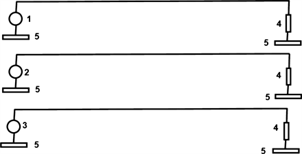
1. Sine wave source with 0 degree phase; 2. Sine wave source with 120 degree phase; 3. Sine wave source with −120 degree phase; 4. Simulation of consumer in the form of resistance - 100 Ohm; 5. Nullifier.
Figure 2. Three wires and three phase systems structures.
think about the reconstruction. But we can use them for transmitting three one wire signals [2] (Figure 3).
Short conclusions from previous works can be formulated as here.
- All energy in three wires of three-phase system can be transmitted in one wire where this wire is the same like in three-phase system (Figure 4).
- So using three wires one can transmit by three times more energy, than in three phase system (see block 3 in Figure 4).
- Three-phase system has important advantage. This system does not radiate energy. This conclusion corresponds to vectors algebra. (The radiation of sum of three vectors with common point and with corners between them 120 degrees equals zero).
- The same advantage can receive and in three wires (not three-phase) system. In this case three signals must be with the same amplitude and the same phases.
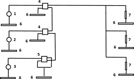
1. Sine wave source with 0 degree phase; 2. Sine wave source with 120 degree phase; 3. Sine wave source with −120 degree phase; 4. Transformer; 5. Inverter - transformer with opposite windings; 6. Nullifier; 7. Simulation of consumer in the form of resistance - 100 Ohm.
Figure 3. Triple one wire system example for simulation.
![]() 1. Sine Source - 230 V, 50 Hz, Phases are 120 degrees; 2, Simulation of consumer in the form of resistance - 100 Ohm; 3. Inverter – one wire transformer with opposite windings; 4. Transformer.
1. Sine Source - 230 V, 50 Hz, Phases are 120 degrees; 2, Simulation of consumer in the form of resistance - 100 Ohm; 3. Inverter – one wire transformer with opposite windings; 4. Transformer.
Figure 4. (a) Converter 2 - 1 with grounding and (b) Converter 2 - 1 with nullifier.
- The simulations show us that this problem can be solved if one of three signals will inverted. The results of simulations give decreasing radiating energy even by 100 times [5] .
We will show that on example “Russian Troika” Figure 5.
Historians claim that the troika as a Russian horse harness appeared at the turn of the 17th-18th centuries. Its appearance in Russia is associated with the desire to increase the speed of driving over long distances. Each horse in the trio gallops at its own gait. There are words of Russian genial writer Gogol.
“... Eh, three! Bird - three, who invented you? To know, you could only have been born among a lively people, in that land that does not like to joke, but has spread out smoothly across half the world, and go count the miles until it hits you in the eyes.” Rereading the lines of the classic, you involuntarily draw an image of a team racing at full speed, and in a trio of horses, the two outer ones always look to the sides, and the central one always looks straight ahead. What explains this? It must be said that the troika is an exclusively Russian invention. Initially, this type of harness was used in courier and postal delivery and transportation of passengers. Later, the meaning changed, and the troika began to be used mainly for ceremonial rides to demonstrate the prowess and strength of the horses and the wealth and luxury of the owner.”
The central horse in such a harness is the root horse. Usually this role was assigned to a representative of the trotting breed, so that the horse would trot all the way, without breaking into a gallop. Side horses, which are called draft horses, do not act as the main draft force. Their task is to maintain the pace set by the root artist and complement the overall concept.
Proposed idea on Figure 5 in the three wires of the former three-phase system (former triple), we transmit three currents. In the middle wire, the current is approximately equal to the sum of the currents in the two outer wires. To prevent this
system from emitting energy, it is proposed to include inverters in the middle wire at the beginning and at the end. Then the current in the middle wire will have reverse polarity [5] [6] and [7] .
Let us remind you. That three-phase signal does not radiate energy. But in proposed here system radiation will be small also due to using invertors in one of wires. There is one more very important property of a single-wire signal. This signal must be used to transmit energy, not information. Therefore, changing the phase components of a single-wire signal does not affect the energy of this signal.
The central horse in such a harness is the root horse. Usually this role was assigned to a representative of the trotting breed, so that the horse would trot all the way, without breaking into a gallop. Side horses, which are called draft horses, do not act as the main draft force. Their task is to maintain the pace set by the root artist and complement the overall concept.
The mechanism of the troika is that the root horse, walking at a wide, sweeping trot, is, as it were, “carried” by galloping harnesses, fastened to the root horse with lines. Thanks to this, all three horses tire more slowly, but maintain a high speed.
Proposed idea in the three wires of the former three-phase system (former triple), we transmit three currents. In the middle wire, the current is approximately equal to the sum of the currents in the two outer wires. To prevent this system from emitting energy, it is proposed to include inverters in the middle wire at the beginning and at the end. Then the current in the middle wire will have reverse polarity. One can give the name for this system “Troika”
Let us remind you. That three-phase signal does not radiate energy. But in proposed here system “Troika” radiation will be small also due to using invertors in one of wires. There is one more very important property of a single-wire signal. This signal must be used to transmit energy, not information. Therefore, changing the phase components of a single-wire signal does not affect the energy of this signal.
For example, we need to transmit some signals using a monopole antenna. Allows these signals one can be summed in a transformer. Output circuit must to connect with nullifier. In this case the phase of input signals can be changed. And energy of output signal will change.
If we give to outputs transformer one wire signal (not several signals). So nullifier will not influence on energy transmitting.
This is not always convenient. But the same scheme can be built using an operational amplifier (where one of two inputs OA inverted signal.) Today OA for power needed for transmitting electrical energy do not exist. But it is possible to do this OA today (Figure 6).
This is not always convenient. But the same scheme can be built using an operational amplifier (one of two inputs OA inverted signal Figure 6 Today OA for power needed for transmitting electrical energy does not exist. But it is possible
![]() 1. Sine Source - 230 V, 50 Hz, Phase 0 degree; 2. Simulation of consumer in the form of resistance - 100 Ohm; 3. Inverter - transformer with opposite windings; Nullifier.
1. Sine Source - 230 V, 50 Hz, Phase 0 degree; 2. Simulation of consumer in the form of resistance - 100 Ohm; 3. Inverter - transformer with opposite windings; Nullifier.
Figure 6. Converter 2 - 1 with inverter.
![]() 1. Sine Source - 230 V, 50 Hz, Phase 0 degree; 2. Simulation of consumer in the form of resistance - 100 Ohm; 3. Operational amplifier; 4. Nullifier
1. Sine Source - 230 V, 50 Hz, Phase 0 degree; 2. Simulation of consumer in the form of resistance - 100 Ohm; 3. Operational amplifier; 4. Nullifier
Figure 7. Converter 2 - 1 with operational amplifier.
to do this OA. (Figure 7).
If we will have a large power OA in Figure 6 and Figure 7, then we can compare between two schemas.
3. Conclusions
What’s the most important thing in this article? Maybe the following?
- Art is what remains.
- But there will always be new brilliant creations.
- In the technical field new “today impossible” solutions will appear.
- Electrical systems may be wireless.
- We will not heat our climate.
- Not artificial, but human intelligence can create something fundamentally new [6] .