A Contention-Based MAC and Routing Protocol for Wireless Sensor Network ()
1. Introduction
Wireless Sensor Network (WSN) is widely used in numerous sensor-based applications recently due to the advancement of micro-sensor systems and mobile ad-hoc network (MANET) technology. Certain important applications in WSN are environmental monitoring system, condition monitoring of industrial machines, security applications, smart cities and healthcare applications. WSN’s technology is widely used in the security applications especially in urban areas. The safety of the residents is guaranteed with the deployment of wireless sensor nodes along with motion sensors and alarm system in a house. Intruders can be detected with the aid of these systems and the intrusion is immediately reported to the house owner [1] . Furthermore, WSN can be utilized in the hospital’s healthcare application to allow real-time health monitoring and emergency alerts. In [2] , the authors have discussed an idea where wireless sensors are installed inside emergency rooms to check patient’s heart rates and blood oxygen levels in real time. Despite the challenges caused by radio noise and interference, the implementation of WSN enhances the efficiency of medical facility [2] . Wearable technology with integrated biomedical sensors is developed in [3] and it offers individual medical assistance using the interactions of real-time body sensors and mobile phones. Besides, the authors in [4] have proposed an Underwater WSN (UWSN) which utilizes ground-based sensor nodes to evaluate the pollution level of a farm. In [5] , WSN-AQSM has been proposed to monitor polluted air. Besides, the utilization of WSN in condition monitoring of industrial machine is more efficient than manual checking. In [6] , wireless sensor nodes are deployed in particular regions of an electrical machine to evaluate the motor’s health condition in terms of motor terminal quantities such as currents, voltages, temperature and so on. A WSN monitoring system for oil and gas pipelines termed REMONG is proposed in [7] . REMONG examines the pipeline leakage by evaluating the temperature and pressure levels of the pipeline fluid at certain points of interest. For smart cities application, a WSN-based traffic system is introduced to monitor road traffic condition [8] . The nodes equipped with magnetic sensors are placed along the roadway to offer real-time traffic monitoring. In addition, the authors in [9] have proposed a WSN-based approach for managing and controlling the street light in the cities.
In WSN, Medium Access Control (MAC) protocol plays an important role in energy saving task. Specifically, MAC protocol controls which node has the rights to access the shared wireless medium at specific time in order to prevent packets collision. The nodes which do not have the rights to occupy the medium are forced to sleep. In other words, MAC protocol utilizes certain duty-cycle algorithms to coordinate nodes for the channel access and occupancy [10] . Several MAC protocols have been proposed recently to address different WSN related issues such as unnecessary energy consumption, packets collision, ineffective channel utilization, etc. [11] . The most popular MAC strategy used is contention-based scheme due to its simplicity and efficiency. Besides, numerous routing protocols have been proposed for sensor-based applications in wireless sensor networks (WSNs). Routing protocol is used to discover and establish optimal routes for multi-hop data transmission from source node to destination node [12] . Single-layer routing strategies rely on maintaining updated routing information and flooding of control packets for data transmission without the interaction of other layers. They are classified as single-layer proactive and reactive routing protocols. Proactive protocols attempt to maintain up-to-date routing tables, with nodes periodically broadcasting routing information to their neighbours, whereas reactive protocols establish routes on demand. Proactive protocols have the disadvantage of exchanging routing information frequently with intermediate nodes, leading to unessential bandwidth utilization and extra control overhead. Frequent updates of routing tables also result in significant energy consumption. Reactive protocols introduce additional delays due to the lack of pre-determined routes, and control packets used for route discovery also results in control overhead. Apart from the single-layer routing strategies, cross-layer design approaches have attracted lots of attentions in developing robust and energy-efficient protocols in WSN. Cross-layer protocols are more efficient in terms of overall network performance as compared to single-layer protocols [13] [14] [15] [16] . Cross-layer design contravenes the rules of the layered protocol and allows the effective interaction between adjacent layers [17] . For instance, the authors in [18] have proposed a cross-layer model that integrates network layer, data link layer and physical layer to achieve energy efficiency. Single-layer routing mechanisms often trade off energy efficiency to achieve reliability and low latency or vice-versa. For instance, DSDV protocol achieves low ETE delay for data transmission but at the cost of high energy consumption per packet and high packet loss probability. Unlike cross-layer design protocols, they can utilize information from multiple layers of the protocol stack to achieve high energy efficiency, reliability and low latency at the same time [17] .
In this article, a novel cross-layer design protocol called Contention/SNIR-Based Forwarding (CSBF) protocol is proposed. Instead of using conventional routing techniques such as periodical exchange of control packets and updates of routing table, CSBF utilizes five novel strategies to achieve effective routing. First and foremost, CSBF exploits the geographical information of sensor nodes to compute the forwarding angle based on destination node’s location. In order to ensure high quality link for data transmission, CSBF computes SNIR between nodes and nearest neighboring node is selected as a relay node to forward data packets. The cooperations of these two strategies improve reliability. Furthermore, Contention-Winner Relay scheme with Sleep Mode is introduced to reduce contention delay and energy consumption. Winners store and directly forward data packets to the next forwarder whereas losing contenders are forced to sleep. Effective data retransmission scheme is also utilized by CSBF. CSBF uses queues and error control frame to achieve one-hop data retransmission. Besides, CSBF incorporates a unique sequence number in every packet’s header to distinguish between a new packet and a duplicated packet, thereby eliminating duplicated packet. The proposed CSBF is compared with other existing routing protocols and the performance metrics used for the analysis are PDR, average ETE delay and energy consumption per packet. The remainder of the article is organized as follows. Section 2 explains the existing strategies utilized by contention-based MAC protocols, single-layer routing protocols and cross-layer protocols. Section 3 explains in depth the proposed mechanisms applied in CSBF and performance metrics used for the performance analysis. Section 4 presents the results and discussion for the performance evaluations of CSBF and other routing protocols. Lastly, Section 5 concludes the paper.
2. Related Works
2.1. Contention-Based MAC Protocols
Contention-based MAC protocols can be further classified into synchronous and asynchronous approaches. In the contention-based mechanisms, nodes contend to access the shared channel prior to data transmission. Only the winner in the contention has the rights to access the channel and forward data packet. Before sending data packet, the node utilizes Carrier Sense Multiple Access (CSMA) mechanism to identify the channel occupancy. If the channel is found busy, the node backoff randomly to defer its transmission. Sensor-MAC (S-MAC) is known as a representative approach in synchronous MAC protocols [19] . The S-MAC protocol uses shared synchronized schedules to reduce energy consumption during idle listening in wireless sensor networks. Nodes undergo active/sleep periods, known as duty cycles, and only activate their radio to send or receive packets. A SYNC message is broadcasted by the sender to its neighbours to initiate the synchronization process. Neighbouring nodes with the same synchronized schedules create a virtual cluster. RTS/CTS/DATA/ACK four-way handshaking is used for data transmission to avoid issues like packets collision, overhearing, and hidden terminal. Adaptive MAC for Critical Mission (ADMC-MAC) is designed to improve energy efficiency [20] . In ADMC-MAC, the duty-cycles of the sensor nodes are dynamically altered based on the traffic loads. Initially, every node broadcasts the synchronization (SYNC) packets which contains the number of neighbouring nodes discovered, node’s transmission queue length, node’s remaining energy and the priority’s order to its neighbour. A cluster head is selected according to the criteria in SYNC. Then, the cluster head employs a regression approach to compute the duty-cycle factor and broadcasts it to the neighbouring nodes. The neighbouring nodes adopt this duty-cycle for data transmission. Berkeley-MAC (B-MAC) is an asynchronous protocol that utilizes low power listening (LPL) technique [21] . LPL allows low power communication without requiring synchronization, which eliminates overhead caused by shared active/sleep schedules. In B-MAC, the sender initially sends a preamble which the transmission duration is longer than the receiver’s sleep duration prior to data transmission. If the received preamble is intended for the receiver, the receiver remains active to receive the data packet. The receiver performs Clear Channel Assessment (CCA) to check the occupancy of the shared channel. QoS-MAC Protocol for Prioritized Data (QPPD-MAC) is proposed in [22] and it is an asynchronous receiver-initiated protocol. QPPD-MAC employs a request-allocation mechanism based on data priority tags and sender’s beacon. The receiver checks for the sender’s priority level upon receiving the beacon and assigns the sender with the highest priority as the winner of the contention. The receiver’s duty-cycle is varied based on its residual energy.
2.2. Single-Layer Proactive Routing Protocols
There exist considerable research works on proactive and reactive routing protocols. In proactive routing protocols, the routing information is exchanged periodically among all nodes to maintain up-to-date route and the routing information is stored in the node’s routing table. The route from source to destination is always available prior to data transmission. Destination Sequenced Distance Vector (DSDV) is a well-known proactive protocol that utilizes Bellman-Ford algorithm [23] . Each node maintains a routing table with potential destinations and their hop counts along with a sequence number assigned by the destination. Routing updates are frequently sent throughout the network to keep updated routing table. DSDV has two approaches such as incremental updates and full dump approach. The incremental updates technique is used in a stable network whereas full dump approach is utilized in highly dynamic networks. The route with the highest sequence number is selected. Moreover, Optimized Link State Routing (OLSR) which is an improved version of traditional link state protocols is proposed in [24] . OLSR utilizes multipoint relays (MPR) techniques to reduce the number of messages transmitted and link state information is created by using MPRs. In contrast to traditional link state protocols that distribute the entire link state information, OLSR provides partial link state information. The multipoint relay sets are selected to cover all two hops neighbouring nodes, and periodic HELLO packets are used to identify the bi-directional link. The packets are only forwarded by MPRs, and the route from source to destination is also established via the MPRs.
Besides, Better Approach To Mobile Ad-hoc Networking (BATMAN) protocol is proposed in [25] . The routing table is established in the network layer. Each node broadcasts an Originator Message (OGM) to inform its neighbours of its existence prior to data transmission. The OGM packet is then rebroadcasted again to the best next hop node and so on. BATMAN uses a decentralization technique to forward data packets to the destination node based on greedy approach, without requiring global knowledge of the entire topology. Sliding windows algorithm is adopted by BATMAN to keep record of the most current sequence number (SQ) and discard the older data.
2.3. Single-Layer Reactive Routing Protocols
Reactive routing scheme only constructs a route from source to destination when necessary. The route is established via route discovery technique which entails the flooding of route request packets throughout the network. Dynamic Source Routing (DSR) protocol utilizes “on-demand” algorithm for routing. DSR consists of two phases such as route discovery and route maintenance procedures [26] . In the route discovery process, a node sends a route request packet to neighbouring nodes, which append their node ID in the packet and broadcast it further. The destination node or the node with the current path to the destination replies with a route reply packet to the source node in reverse direction. The source node then initiates routing procedures and stores the route in its route cache. Route cache is utilized to reduce overhead by searching for a route that corresponds to the requested destination before broadcasting a route request packet further. DSR selects the shortest route to the destination. Furthermore, Ad hoc On-demand Distance Vector (AODV) protocol is developed to discover and establish routes on-demand instead of maintaining up-to-date routing information [27] , which could reduce the broadcasted control messages. Prior to data transmission, the source node checks its routing table for a viable route to the destination. If the route is not found, the source node initiates the route discovery process by broadcasting a Route Request (RREQ) packet. Intermediate nodes with a destination sequence number equal to or larger than the sequence number in the RREQ header respond to the RREQ, and the first node from which data was received is stored in the routing table. A reverse route is built using this recorded data, and a Route Reply (RREP) packet is forwarded via the designated reverse route. The forward route entry is stored in the routing table using symmetric links.
The authors in [28] have proposed Labeled Distance Routing (LDR) protocol which utilizes distance labels instead of sequence numbers to guarantee loop-free routing. RREQ packets are distributed within a tree that follows a rigid ordering of feasible distances along successor routes, using the reverse-path flooding strategy. The relevant intermediate nodes compute route by caching the route information for certain durations, and RREP packets are forwarded back to source by the destination node or relay nodes that have a valid route to the destination via the reverse path.
2.4. Cross-Layer Design Approaches
Numerous studies have proven that cross-layer design techniques provide better efficiency on routing comparing to single layer routing approaches due to the interactions between multiple layers [29] [30] [31] . MAC-CROSS is proposed to address the compulsory wake-up issue by having only selected nodes participate in data forwarding, while others sleep [32] . It uses an address conversion scheme to map IP addresses to MAC addresses and a greedy approach to route data packets. The RTS and CTS frames contain destination and next hop addresses. Moreover, a position-based Cross-Layer Greedy Routing (CL-GR) protocol is proposed to tackle the issue of radio irregularity phenomenon [33] . A packet is forwarded via symmetrical links, based on computed path loss and distance experienced by the links. CL-GR outperforms other location-based protocols such as E-GR and COP-GARE. Furthermore, XLM cross-layer module is proposed in [34] . XLM protocol differs from other traditional architecture-based protocols and relies on the initiative concepts such as distributed duty cycle operation, received-based operation, local congestion control, and initiative determination. Intermediate nodes depend on several parameters to join the communication such as packet rate transmitted by relay node, node’s buffer occupation, signal noise ratio (SNR) of an RTS packet, and node’s residual energy. These cross-layering functionalities ensure reliable communication and energy efficiency. Results have shown that XLM is better than single-layer stack protocols in terms of energy efficiency and link quality.
Joint Routing, Power control and Random access Algorithm (JRPRA) is proposed for the single-sink wireless sensor networks [35] . It utilizes information from the physical, MAC, and routing layers to achieve energy efficiency and optimal route selection. The protocol uses the Joint Routing and Power Control Algorithm (JRPA) to manage transmission power and compute routes. JRPRA employs correlated data collection techniques and the Slepian-Wolf algorithm to address non-convex optimization issues. Link capacity is also modified based on traffic load to prolong network lifetime. Cross Layer Optimal Design (CLOD) protocol is proposed in [36] . CLOD uses compressed sensing to reduce the number of transmitted bits, and appropriate resource allocation to mitigate link-level congestion at the data link layer. CLOD’s computational complexity is minimized significantly with the assumption of constant link capacity. It achieves optimal overall network performance under low network traffic.
3. Key Features of CSBF Protocol
Contention/SNIR-Based Forwarding (CSBF) protocol utilizes DATA-ACK two-ways handshake mechanism instead of traditional four ways handshake mechanism for data transmission. There are five key features of CSBF protocol such as adaptive forwarding angle based on destination’s position, contention-winner relay scheme with sleep mode, data retransmission scheme, duplicated packet elimination technique and SNIR metric as a deciding parameter for data routing. CSBF establishes an adaptive forwarding angle by exploiting the geographic information of nodes in the network. Sink node broadcasts the position beacon to every node in the network prior to data transmission. Furthermore, the contention-winner relay scheme is utilized where the selected winners remain as default forwarders and forward packets without going through the contention process again. Sleep mode technique is implemented in CSBF where the losers in contention will go to sleep. Also, CSBF incorporates SNIR metric that acts as the deciding factor for data forwarding. Duplicated packet elimination is adopted to detect and eliminate redundant packets. The proposed features of CSBF are explained in detail in the next sections. Also, the operation of CSBF protocol is explained thoroughly in the Section 3.6.
3.1. Adaptive Forwarding Angle Based on Destination’s Position
Unnecessary route is formed when a data packet is routed towards source node or intermediate nodes which cannot reach destination. Therefore, the scheme of adaptive forwarding angle based on destination’s position is employed to address this problem and this scheme is illustrated in Figure 1. According to [37] , 60˚ forwarding angle offers the best trade-off between unicast efficiency, ETE delay and packet delivery ratio. Prior to data transmission, the destination node which is indicated by D initially broadcasts the beacon that consists of its geographic information to every node in the network. Upon reception of the beacon, all nodes including source node (S) and intermediate nodes (N1, N2, N3, N4) exploit the beacon’s information and compute 60˚ forwarding angle based on destination node’s position. Node N1 and N2 are eligible to contend because they are located within the forwarding angle computed by node S. In contrast, node N3 and N4 discard the data packet as they are not located within the forwarding zone. The forwarding angle is calculated as follows:
(1)
if
, then simply adds one more expression which is shown in Equation (2). Otherwise, if
, skips Equation (2) and proceeds to Equation (3).
(2)
(3)
and the results for Equation (3) should be:
(4)
![]()
Figure 1. Illustration of the adaptive forwarding angle based on destination node’s position scheme.
where
and
denote the forwarding angles in radian and degree units respectively.
denotes the position vector of y-coordinate for destination node and
denotes the position vector of y-coordinate for the relay nodes.
and
indicate the position vector of x-coordinate for destination and intermediate nodes respectively. Nodes discard the packet and do not participate in the contention process when they do not satisfy the condition shown in Equation (4).
3.2. SNIR Metric as a Routing Parameter
SNIR metric is used as a routing parameter for data transmission in order to ensure high quality of a link. The network is set up with a group of static sensor nodes. Among the sensor nodes, one of them is sink node and another one is source node. The rest of the nodes are located between source and sink nodes and they act as intermediate nodes which relay data packet from source to destination. Every node computes the SNIR values after receiving the packet. To achieve reliable data transmission, the SNIR values should be greater than a minimum threshold
. Received power in relation to transmission distance between the transmitter and receiver, transmitting power and signal propagation model affects the SNIR [38] . Log-normal shadowing path loss model is used instead of free space path loss because it is not practical to neglect the shadowing effect in real condition. The received power
of node β can be calculated as:
(5)
where
denotes the transmitting power of node α,
represents the path loss at reference distance
, n is the path loss exponent,
indicates the distance between nodes α and node β, and
denotes the zero-mean Gaussian random variable with standard deviation σ. After obtaining the value of
, the computed SNIR which is denoted as
between node α (transmitter) and node β (receiver) can be derived as:
(6)
where
refers to the received power of ith transmitter and the interference signals is defined as the total of received power from other transmitters.
is the background noise detected at node β. Based on the derivation of
, SNIR metric
can be computed as:
(7)
where
is the SNIR threshold and
is the computed SNIR between nodes α and β. Also, the contention timer
can be written as:
(8)
where
denotes the constant variable for contention timer in milliseconds (ms).
3.3. Contention-Winner Relay Scheme with Sleep Mode
High ETE delay is the major issue for contention-based mechanisms. This is because every node has to contend every round for the relay selection process prior to data transmission. CSBF improves the contention-based strategy by implementing the contention-winner relay scheme. In CSBF, the node declares itself as “winner” and stays as default forwarder after winning the contention. The winner directly forwards all packets to next relay node without going through the contention procedure again. The losers in the contention process will go to sleep mode instead of staying idle after receiving the broadcast of the data packet from the winner. By adopting sleep mode technique, unnecessary energy consumption can be reduced significantly.
3.4. Duplicated Data Packet Elimination Technique
Transmission of the duplicated data packets results in network congestion [39] . Network congestion causes packets collision which degrades the network performance in terms of packet delivery ratio. CSBF mitigates this issue by utilizing duplicated packet elimination technique. A unique sequence number is assigned to every data packet and it is stored in the packet’s header. Every potential relay node records the sequence number of the data packet after receiving it. By checking the sequence number, the relay node can differentiate between a duplicated packet and a new packet, thereby discards the duplicated packet.
3.5. Data Retransmission Scheme
Data retransmission scheme is applied in CSBF. This scheme employs two queues or buffers and an error control frame to achieve one-hop retransmission [40] . The first queue is Contention/Forward queue and data packet is stored in this queue prior to the contention. The packet is withdrawn from this queue for transmission purpose after the node wins the contention. The second queue is Retransmission Queue. A copy of the data is stored in the Retransmission Queue before forwarding the data packet. The data packet is accessed from this queue for retransmission if the node receives the Error Control frame from the intended recipient which indicates unsuccessful reception. The node performs random backoff to retransmit the packet. The Error Control frame contains the source address of the recipient.
3.6. Description of the Algorithms Applied in the CSBF Protocol
This section gives an in-depth explanation on the Algorithms applied in the operations of CSBF protocol. The pseudocodes shown highlight the procedures for Algorithms 1-9 that are applied in CSBF protocol’s operations. The key variables used in the Algorithms are summarized in Table 1.
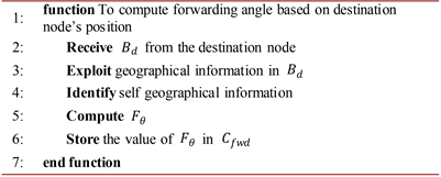
Algorithm 1. Pseudocode for the Node’s computation of forwarding angle based on destination’s location.
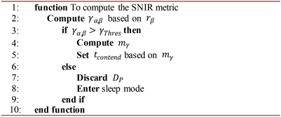
Algorithm 2. Pseudocode for the computation of SNIR metric.
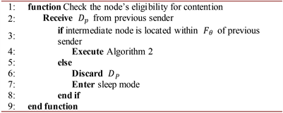
Algorithm 3. Pseudocode for the Node’s eligibility for contention.
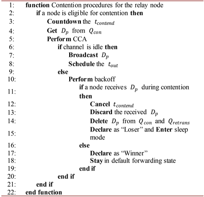
Algorithm 4. Pseudocode for the contention-winner relay scheme.
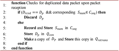
Algorithm 5. Pseudocode for the duplicated data packet elimination mechanism.
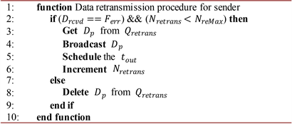
Algorithm 6. Pseudocode for the Sender’s data retransmission technique.
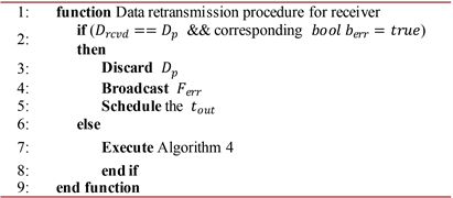
Algorithm 7. Pseudocode for the receiver’s data retransmission technique.
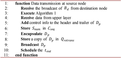
Algorithm 8. Pseudocode for the source node’s data transmission scheme.
Algorithm 1 emphasizes the procedures when a node computes the forwarding angle based on destination node’s position. Initially, the destination node broadcasts the beacon
consisting of its own position information to all nodes in the network. Upon reception of
, the node exploits sink’s geographical information in
. At the same time, every node identifies self location information. Then, the node utilizes both self and sink’s geographical knowledge to
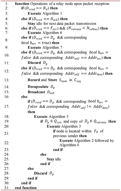
Algorithm 9. Pseudocode for the operations of a relay node upon packet reception.
compute the forwarding angle
in radian unit with respect to sink’s location by using Equation (1).
will be converted to forwarding angle
in degree unit. The computed forwarding angle is stored in the forwarding cache
of the node. After computing the forwarding angle, the source node receives data from the upper layer and broadcasts data packets to the intermediate nodes. Algorithm 2 depicts the procedures for the computation of SNIR metric. When a node receives data packet
from the source node or previous sender, it will compute the SNIR value
based on
. If
is greater than the SNIR threshold
, then the SNIR metric
is computed using Equations (5) - (8), otherwise the data packet is discarded. The contention timer
is then computed based on
. Algorithm 3 highlights the node’s eligibility for contention. After receiving
, the node checks whether or not it is located within the 60˚ forwarding angle of the previous sender. If the node is located within the predetermined forwarding angle, then it is eligible to contend for the forwarding rights. Otherwise, the node does not satisfy the contention criterion and so it discards
and enters sleep mode. The eligible contenders
![]()
Table 1. Key variables used in the CSBF algorithms.
execute Algorithm 2 that involves the process of computing SNIR. Algorithm 4 explains the procedures involved in Contention-Winner Relay Scheme. When a node is ready to contend for the forwarding rights, it will countdown the
Upon expiry of
, the node gets
from Contend queue
and performs CCA to check for the channel occupancy before broadcasting it. If the channel is found busy, the node performs random backoff to defer the data transmission whereas if the channel is idle, the node immediately broadcasts
. The first node to broadcast
wins the contention and declared as “Winner”. The Winner stays in default forwarding phase and forwards next
without the need to contend again. On the other hand, if a node receives other
before the timeout of
, it cancels its own contention timer, discards the received
, declares itself as “Loser” and enters sleep mode. Also, the node deletes
from
and Retransmission queue
. Algorithm 5 presents the process for a node to check for duplicated data packet. Upon reception of
, the node checks for the records of
in Sequence number cache
. If
is available in
, then the node identifies the received
as a duplicated data and discards it. On the contrary, if
is not present in the
, the node will update the respective
in the
. The received
is stored in
and a copy of
is stored in
.
Besides, Algorithm 6 and Algorithm 7 highlight the data retransmission procedures for the sender and receiver respectively. In Algorithm 6, if the sender receives Error Control frame
from the intended receiver and the number of retransmissions
is less than the maximum number of retransmissions
, it gets
from the
, forwards it again and schedules the transmission timeout
.
is incremented by one after the retransmission process. In Algorithm 7, upon reception of
, the receiver first checks for the bits error of
. If bits error is detected, the receiver indicates that the received
is a corrupted packet and discards it. Then, the receiver forwards
and schedules
. In contrast, if
does not contain bit error, the receiver initiates Algorithm 4. Furthermore, Algorithm 8 explains the data transmission technique for source node. The source node receives
from the destination node and executes Algorithm 1 to compute forwarding angle. Upon reception of data from the upper layer, the source node adds control information to the header and trailer of
. Then the source node encapsulates
, make a copy of
and stores it in
. Next, the source node broadcasts
and schedules the
. Algorithm 9 shows the operations of a relay node upon packet reception. When a relay node receives a packet, it initially checks for the received packet type. If the packet is a
, then the node executes the function of Algorithm 1 which is the computation of forwarding angle. Besides, if the received packet is a
, the node stays idle until the next data packet transmission. However, if the relay node receives a
and
is less than
, then Algorithm 6 which indicates the procedures for Data Retransmission Technique at Sender is executed. Besides, when the node receives a corrupted
, it initiates Algorithm 7 that performs the Data Retransmission procedures for the recipient. Moreover, if a node receives a normal
and the node’s MAC address
matches the incorporated destination MAC address
in
, it means that the node itself is a destination node. The node records the
, decapsulates
and forwards acknowledgement packet
to the previous one hop sender. In contrast, if
does not match
, then the node initiates Algorithm 5 to check for the duplicated packet. If
is not a duplicated packet, the node performs next action by checking the availability of
in
and a copy of
in
. If
and its copy are present in both queues, the node initiates Algorithm 3 to check for the contention’s eligibility. Otherwise, the node remains idle. If the node is located within
of the previous sender, then it is eligible for contention. Finally, the node executes Algorithm 2 which implies the procedure for the computation of SNIR metric, then followed by Algorithm 4 indicating the procedure for Contention-Winner Relay Scheme with Sleep Mode. However, if
of a node matches
, it discards the received
since the node is a source node. Figure 2 illustrates the simplified flowchart that summarizes the CSBF algorithms for a relay node.
![]()
Figure 2. Simplified flowchart of the CSBF algorithms for an intermediate node.
3.7. Performance Metrics
This section explains about the performance metrics in detail. Three performance metrics such as average end-to-end (ETE) delay, packet delivery ration (PDR) and energy consumption per data packet are used for the comparative analysis of the protocols.
Average End-to-End (ETE) delay: End-to-End (ETE) delay refers to the total amount of duration it takes for a data packet generated at source node to the time it reaches destination node [41] . The elements of the ETE delay include processing, queuing, propagation and transmission delays. The calculation of ETE delay is written as:
(9)
where
is the duration for ETE delay,
denotes the instantaneous arrival time of a packet at the destination and
refers to the instantaneous departure time of a packet from the source. Average ETE delay,
can be derived as:
(10)
where
indicates the ETE delay of ith packet and N refers to the number of the received packet at sink. Therefore, average ETE delay refers to the ratio of the addition of all ETE delay of packets received at the sink node to the number of received packets. Packet dropped is not included in the calculation.
Packet Delivery Ratio (PDR): Packet Delivery Ratio (PDR) refers to the ratio of the total number of packets received successfully by the destination node to the total number of packets transmitted by source node [41] . PDR can be calculated as:
(11)
Here,
refers to the total number of packets received by the destination node whereas
refers to the total number of packets transmitted by source node. PDR can be also expressed in percentage (%) format.
Energy consumption per packet: The energy consumption per packet
is defined as the energy consumed by single packet that is received at the destination node [41] which can be written as:
(12)
where
is total energy consumption and
is the number of packets successfully received at the destination or sink node.
4. Results and Discussion
Extensive simulations and testing of the protocols are carried out using OMNeT++ network simulator [42] . The performance of CSBF is compared with other existing routing protocols such as AODV and DSDV. The details regarding the simulation setup, system parameters performance metrics and propagation model used are explained next.
4.1. Simulation Setup and System Parameters
The performance is analyzed in terms of varying payload size, number of nodes and packet interarrival time. The payload size varies from 10 bytes to 90 bytes with incremental of 20 bytes. Besides, the number of nodes varies from 10 to 50 nodes with incremental of 10 nodes. The nodes are randomly distributed in the network. Every sensor node is assumed to be equipped with GPS they are static. Figure 3 illustrates the network topology which consists of 50 nodes. In the network, there is one source node which generate data packets and one destination node which broadcast beacon signals, collects and sends data to the application layer for data processing. Prior to data transmission, the sink node initially broadcasts a beacon frame and we assume that the transmission power of the sink is sufficient to reach all nodes. After broadcasting the beacon, the sink lowers its transmission power which is same as the transmission power of other nodes. System parameters are predefined for the results evaluation. Table 2 highlights the system parameters defined for the simulation.
4.2. Propagation Model Used
Log-normal shadowing propagation model is used in the simulation in order to simulate a more realistic wireless channel. This model is used instead of free space path loss is due to different sources of interference exist in the real environment. Free space path loss model assumes that the space is in vacuum state without considering any interference and it is not practical [39] . Log-normal shadowing model can be written as:
(13)
![]()
Figure 3. Network topolgy with 50 nodes in OMNeT++ simulator.
where d refers to the distance between transmitter and receiver and
is the reference distance, α refers to the signal decays at certain rate, and
denotes as the noise mapped as a zero mean Gaussian random variable with σ indicating the standard deviation. The simulation results for the protocols are discussed next.
4.3. Simulation Results and Performance Comparison of the Protocols
In this section, the simulation results for CSBF, AODV and DSDV protocols are compared and discussed in detail. The protocols are tested in terms of varying payload size, number of nodes and packet interarrival time.
4.3.1. The Impact of Different Number of Nodes
In this subsection, we will be evaluating the influence of varying number of nodes on the performance of the protocols. The number of nodes varies from 10 nodes to 50 nodes with the incremental steps of 10 nodes. The packet interarrival time remains constant at 0.2 s and the payload size of the data packet is fixed at 90 bytes.
Figure 4 shows the results of energy consumption per packet with respect to varying node density or number of nodes. Increase in node density results in the increase of energy consumption per data packet for all the protocols. The increase in energy consumption per packet is due to the increase of the overall
![]()
Figure 4. Energy consumption per packet versus number of nodes.
energy consumption among all the sensor nodes. Energy is used during transmission and reception of data packets among the nodes. Idle listening of nodes also consumes energy. CSBF with the mean values of 41.56 mJ/packet yields the lowest energy consumption per packet comparing to AODV (mean values of 49.096 mJ/packet) and DSDV (mean values of 53.547 mJ/packet). This is because the CSBF’s contention-winner relay technique allows only the winning contender or winner to relay data packets while other nodes enter sleep mode. This can reduce unnecessary energy consumption caused by idle listening. Another reason that makes CSBF the most energy efficient protocol is CSBF has the lowest packet loss at the destination node. Lack of sleep mode implementation in AODV and DSDV causes unnecessary energy consumption where the nodes remain idle even if there is no event occurs. Besides, AODV utilizes RREQ and RREP packets to establish routes and broadcasts of HELLO messages cause high energy used for control packet’s transmission. As for DSDV, huge amounts of energy is consumed for maintaining updated routing table among nodes. Besides, periodically broadcast of HELLO messages to check for the presence of neighborhood nodes also causes high energy consumption in DSDV.
Figure 5 presents the results of PDR versus varying number of nodes. It can be observed that PDR for DSDV and AODV protocols are decreasing with the increase in the number of sensor nodes whereas CSBF yields the highest PDR performance and remains unaffected by node density. This is due to the ineffective routing techniques adopted by AODV and DSDV. Higher number of nodes causes more control overheads. In DSDV, routing updates are frequently forwarded throughout the network. Frequent exchange of routing information could result in network congestion and hence increases the probability of packets collision. Besides, AODV floods the network with RREQ and RREP control packets to discover routes for data transmission. Also, AODV periodically
broadcast HELLO message to check the link validity. Flooding of control packets lead to large amount of overhead. The increase of node density increases the number of control packets thereby results in higher chances of packets collision. CSBF yields the highest PDR performance compared to other protocols due to its adaptive forwarding angle and SNIR metrics. The implementation of the forwarding angle allows the relay nodes to forward data packets towards the direction of the destination node whereas SNIR routing metric enables the nodes to choose the high-quality link for data forwarding. The cooperation of these two mechanisms is to guarantee successful transmission of the data packets from source to destination. The average PDR performance gains of CSBF over DSDV and AODV are 3.65% and 1.03% respectively.
Figure 6 depicts the results of average ETE delay versus different number of nodes. The average ETE delay for all protocols increase when we increase the number of nodes. This is because there are increasing number of relay nodes in between source node and sink node. More nodes in the path between source and destination nodes means there are more hops and data packet may take longer delays traversing from source to sink nodes. The delays include queuing, processing, propagation and transmission delays. DSDV yields the lowest average ETE delay among the protocols due to its incremental updates mechanism. With this mechanism, DSDV manages to maintain neighborhood routing tables by broadcasting routing information regularly and route is available all the time. However, this comes at the expense of high energy consumption per packet and poor PDR performance. This can be proved in the results obtained in Figure 4
![]()
Figure 6. Average ETE delay versus number of nodes.
and Figure 5 DSDV has to use significant amount of energy to broadcast neighbors entries periodically and utilize large control overheads to achieve low latency in routing. Besides, CSBF performs better than AODV in terms of average ETE delay. This is due to the contention-winner relay scheme in CSBF. With this scheme, the relay node stores and forwards data without the need to contend again for the forwarding right and hence reducing contention delay. In addition, AODV has the highest ETE delay due to its route discovery mechanism. AODV employs control packets such as RREQ and RREP to configure routes. The network will be flooded with RREQ packet until the destination node is discovered. Once the destination node is found, RREP packet is generated and sent back to the source node. The transmission of RREQ and RREP incurs long delays. The average values of the ETE delay of CSBF, DSDV and AODV are 7.87 ms, 7.09 ms and 20.19 ms respectively.
4.3.2. The Impact of Different Payload Size
This subsection analyses the influence of varying payload size on the performance of the protocols. The payload size varies from 10 bytes to 90 bytes with the incremental steps of 20 bytes. The number of nodes is fixed at 50 nodes and the packet interarrival time remains constant at 0.2 s.
Figure 7 presents the results of energy consumption per packet with respect to different payload size. For DSDV and AODV, the energy consumption per packet increase with the increase of payload size. The rising trend in energy used per data packet is because of the packet loss at sink node has significantly
![]()
Figure 7. Energy consumption per packet versus payload size.
increased for a larger payload size packet. Larger payload size packet increases the probability of channel access failure. Here, CSBF yields the most consistent and highest energy efficiency compared to AODV and DSDV. The average values of the energy consumption per packet for CSBF, AODV and DSDV are 66.989 mJ/packet, 79.377 mJ/packet and 89.304 mJ/packet respectively. The overall energy consumption in CSBF is remarkably less due to the sleep mode implementation. Energy is saved when the sensor nodes which are not involved in routing process are put into sleep mode. Comparing to other protocols, the packet loss at sink is comparatively lesser in CSBF due to the adaptive forwarding angle and SNIR metric. With these two proposed mechanisms, data is forwarded via the highest quality link towards destination node. Besides, AODV shows higher energy consumption per packet than CSBF is due to the utilization of the control packets in route establishment. Furthermore, DSDV consumes the highest energy in transmitting a data packet is because of the usage of overall energy. In particular, periodical broadcast of routing information among nodes consumes significant amount of energy. Lack of energy saving scheme in DSDV and AODV is also the root cause of higher energy consumption per packet.
Figure 8 illustrates the result of PDR versus varying payload size. CSBF shows the highest PDR performance as compared to AODV and DSDV protocols. This is because CSBF has the capability to route data packets towards sink node by adopting the predefined forwarding angle technique. Furthermore, CSBF guarantees reliable data transmission by utilizing SNIR routing parameter. Besides, the PDR performance of AODV decreases as the payload size increases. In AODV, the network is flooded with control packets and the data packet with
larger payload size could result in higher chances of buffer overflow. Buffer overflow causes packet drop due to insufficient storage to store data. DSDV yields the lowest PDR performance due to the frequent exchange of routing entries which may lead to packets collision. Packets with larger payload size occupy the channel for longer durations and they might collide with other broadcasted packets. The PDR performance gains of CSBF over DSDV and AODV are 6.3% and 2.51% respectively.
The results of average ETE delay versus varying payload size is demonstrated in Figure 9. It can be observed that average ETE delay increases with the increase of payload size for all protocols. The reason is larger payload size packet has longer channel access and occupancy delays, hence leads to the increase of ETE delay. DSDV yields the lowest ETE delay followed by CSBF. This is because DSDV maintains up-to-date routing table by proactively exchanging routing information but at the cost of high energy consumption and heavy packet redundancy which leads to high packet loss probability. This tradeoff between PDR, energy efficiency and ETE delay can be observed in Figures 7-9. Besides, CSBF protocol allows the winners to stay as default forwarders and directly forward data packets without going through the contention process again which causes delay. AODV has the highest ETE delay due to the long delays incurred in discovering route from source to destination for data transmission. The mean values of the ETE delay for CSBF, DSDV and AODV are 8.41 ms, 7.71 ms, and 42.83 ms respectively.
![]()
Figure 9. Average ETE delay versus payload size.
4.3.3. The Impact of Different Packet Interarrival Time
This subsection discusses the impact of varying packet interarrival time on the performance of the protocols. The packet interarrival time varies from 0.2 s, 0.25 s, 0.333 s, 0.5 s, and 1 s. The payload size remains constant at 90 bytes whereas the nodes density is fixed at 50 nodes.
Figure 10 illustrates the result of PDR versus different packet interarrival time. It can be seen that PDR for every protocol increases with the increase of packet interarrival time. With higher packet interarrival time, the packet generation rate at source node is lower which corresponds to lesser traffic loads and ultimately results in lower packets collision probability. CSBF has the highest PDR performance among the protocols due to its effective relay selection approach. In CSBF, data packet is always routed towards destination node with the implementation of 60˚ forwarding angle algorithm. Also, with the computation of SNIR metric, CSBF will choose the highest quality link for data transmission. Besides, AODV adopts the flooding technique and Dijkstra’s algorithm to compute route. However, flooding of control packets results in extra overheads and increase the chances of packets collision. The application of Dijkstra’s algorithm in AODV is unreliable because this algorithm only considers the shortest path for route computation and neglects the link’s quality for data transmission. DSDV yields the lowest PDR performance when compared to CSBF and AODV. This is because nodes periodically broadcast the contents of their routing table to neighborhood nodes and this leads to network congestion, thereby increasing packets collision possibility. Besides, the HELLO control packets broadcasted by DSDV most likely collides with the in-flight packets when the traffic loads are high. The PDR performance gains of CSBF over DSDV and AODV are 6.47% and 2.34% respectively.
![]()
Figure 10. PDR versus packet interarrival time.
Figure 11 depicts the result of energy consumption per packet versus varying packet interarrival time. The performance of the energy consumption per packet for all protocols increases with the rising of packet interarrival time. This is because the packets received successfully at destination node has increased with lesser traffic loads. CSBF yields the lowest energy used per packet when compared to other protocols. Again, the contention-winner relay scheme with sleep mode utilized by CSBF eliminates unessential idle listening of nodes and enhances the energy efficiency. Besides, AODV uses energy to broadcast RREQ and RREP packets to establish route prior to data transmission. DSDV shows the highest energy consumption per packet. This is because DSDV uses most energy in constructing and maintaining routing table in every node. It compensates high energy consumption to achieve low ETE delay performance. This can be seen in the results obtained in Figure 11 and Figure 12. DSDV achieves low transmission delay by broadcasting neighbourhood routing information globally to maintain route. However, this could lead to redundant control overheads which will cause high overall energy consumption and increase the packet loss at sink. The mean values of the energy consumption per packet for CSBF, AODV and DSDV are 152.94 mJ/packet, 180.74 mJ/packet and 208.15 mJ/packet respectively.
Moreover, the performance of the average ETE delay with respect to varying packet interarrival time is illustrated in Figure 12. Here, the average ETE delay for all protocols increase with the increase of packet interarrival time. The reason for this increasing trend is due to the packet reception rate at sink node over
![]()
Figure 11. Energy consumption per packet versus packet interarrival time.
![]()
Figure 12. Average ETE delay versus packet interarrival time.
a certain period is lower for higher packet interarrival time. DSDV shows the lowest ETE delay followed by CSBF. In DSDV, route is always available for data transmission since nodes frequently broadcast and share the information of their routing tables with other nodes and hence route discovery time is mitigated. Besides, CSBF yields slightly higher ETE delay than DSDV is due to more sensor nodes involve in routing as SNIR metric allows node to choose the nearest intermediate node to forward data packet. This results in queuing and transmission delays. Furthermore, AODV yields the highest ETE delay, and this is due to the long delay caused by route discovery mechanism. AODV will only broadcast RREQ and RREP control packets to find route whenever there is demand for data transmission. The average values of the ETE delay for CSBF, DSDV and AODV are 11.37 ms, 9.77 ms and 44.5 ms respectively.
5. Conclusions
In conclusion, reliable and efficient protocol is vital for a robust network. Conventional routing protocols such as DSDV and AODV utilize single-layer routing approach such as periodical exchange of control packets and maintaining up-to-date routing table to establish route for data transmission. However, these kinds of routing strategies are not optimal for the network performance in terms of energy efficiency and reliability. This research work has proposed a contention-based MAC and routing protocol called CSBF that utilizes cross-layer design approach. CSBF uses geographical information of sensor nodes to route data packets towards the direction of the destination node. By adopting the SNIR routing parameter, the sender chooses the nearest neighbouring node to relay data packet and hence ensuring high quality link for data transmission. Additionally, contention-winner relay scheme with sleep mode is adopted to allow only the winner nodes to relay data packets without the interruption of other losing contenders. The losers which do not have the forwarding rights enter sleep mode right after the contention. This can reduce packets collision and unnecessary energy consumption for idle listening.
Based on the simulation results, CSBF outperforms AODV and DSDV in terms of PDR and energy consumption per packet without the trade-off of any important performance metrics. In the case of ETE delay performance, DSDV yields the lowest ETE delay because route is always available prior to data transmission. However, this comes at the expense of poor network performance in terms of energy efficiency and PDR. This is due to the flooding of routing information among sensor nodes which ultimately causes network congestion and high energy consumption. Furthermore, CSBF has the most consistent results for every performance comparing to the rest of the protocols. However, the main constraint of CSBF protocol is the uneven distributed of nodes’ energy consumption. As for future works, the residual energy of sensor nodes will be incorporated in CSBF and considered as a routing parameter. Specifically, nodes with the residual energy which are higher than a certain threshold are allowed to forward data packets. With this implementation, the energy consumption of nodes can be equally distributed and thereby prolonging network lifetime. Besides, further testing and simulations for other parameters and scenarios should be carried out. Mobility of nodes should also be considered in the simulation configuration.
Fund
This research is supported by Centre for Graduate Studies (CGS) and Yayasan Universiti Teknologi PETRONAS Fundamental Research Grant (YUTP-FRG) under Grant No. 015LC0-389.