1. Introduction
Conceptually, the classical computer is based on the Turing Machine model. The quantum Turing machine is very similar to the classical Turing machine, but the head of the machine, the control automaton and the tape of the machine are in quantum states. The quantum Turing machine can perform calculations in parallel by using quantum properties such as superposition and entanglement. The quantum system always evolves reversibly, which means that one can determine the earlier state of the system by going backwards. Classical circuits are normally irreversible, which means that they lose information during generation of outputs [1] [2] . Permutative quantum circuits are built with reversible gates which have the same number of inputs as outputs and exhibit one-to-one mapping between input and output states. Our interest is in creating a complete methodology to design quantum circuits for arbitrary quantum state machines. A significant part of this methodology is to design binary reversible quantum circuits (described by permutative matrices). Our new method to design such circuits uses only NOT, CNOT and CCNOT (Toffoli) gates. 2*2 Feynman gates are also called CNOT gates. 3*3 Toffoli gates are called CCNOT gates. Larger gates of this type (4*4 Toffoli gates and beyond) are called generalized Toffoli gates. The NOT gate inverts a single qubit, the CNOT gate inverts the target qubit if the control qubit is in state |1〉, the Toffoli and generalized Toffoli gates invert the target qubit if all control qubits are in state |1〉. Quantum Automata (Quantum State Machines, Quantum Finite State Machines) have quantum states instead of the classically determined states [3] [4] [5] [6] [7] . In the most general quantum state machines, the input states, internal states and output states can be quantum states. Currently our method only deals with reversible state machines but it can be applied to Quantum State machines. Similar to quantum combinational circuits, the quantum states of Quantum State Machine can be superposed or entangled [8] . In this paper we restrict our research to permutative automata (we will use this name to describe automata that have circuits described with permutative matrices, by analogy to permutative quantum circuits). These automata are not concerned with superposition and entanglement, but will be easily extended to general quantum state machines in our coming research. Note also that for simplicity, the method presented in this paper relates only to completely specified quantum state machines and those that are used in robotics, thus having no stop states. It is possible to extend our method to incompletely specified state machines, as well as to machines with stop states.
Our previous work on the realization of quantum automata used various codes close to the shortest length codes for encoding internal states [9] . However, several examples suggest that it is better to use the “one hot” encoding, similar to the encodings used in classical FPGAs [10] . The synthesis method presented in this paper utilizes one hot encoding which means that one bit of the state vector (state encoding) is 1 for every state while all other bits in the vector are zeros. This means that the sequential permutative state machine can have only one state in value 1 at a time. If the classical automaton has N internal states, this means that N state variables (flip flops) are required. Observe however that if a superposed input is given to the corresponding quantum state machine, the machine can be in a superposition of multiple one-hot-encoded states. One hot encoding of a quantum automaton has some general advantages including: simplification of design, simplification of testing procedures, reducing quantum cost and increasing speed. This encoding method means that all sub-functions (usually products of literals) in equations that lead to a certain state (internal or output state) are disjoint. Thus the OR logic operators can be replaced by EXOR operators, leading to the Disjoint Sum of Products logic equations. We thus use the Boolean Algebra Law assuming disjoint functions, and thus, A + B = A Å B. Based on the formula A + B = A Å B Å AB and assuming that functions A and B are disjoint (AB = 0), we use formula A + B = A Å B as a fundament of our method. Such a property is important in this application since the foundational computing gates, e.g., the CNOT, are based on EXOR logic rather than OR logic.
Recently, synthesis of Sequential Quantum Circuits became an active area of research [3] [9] [11] [12] [13] , but this paper is the first to present a method to synthesize Sequential Quantum Circuits directly from flowcharts. One of the preliminary steps to implement a given functionality (for instance for a behavioral robot) is to represent it as a flowchart. The interpretation of a flowchart is presented in by Morris Mano in several of his well-known textbooks [14] . This type of initial specification of standard automata is popular in programming and also in traditional hardware design. Although hardware description languages such as Verilog and VHDL are currently used for synthesis, some compilers of these languages create intermediary data structures similar to flowcharts. Therefore, we believe that flowcharts should also be used for quantum state machines as an intermediary step in a quantum compiler [15] .
There are many methods that convert flowcharts (also called algorithmic state machines [14] ) to standard graphs or state tables of finite state machines. Then standard logic synthesis methods are used to realize the state tables using SOP (Sum of Products) expressions. These methods do not work well for quantum circuits, especially for multi-output circuits, as they lose the information about common sub-expressions and use expensive gates such as many-input generalized Toffoli gates in the case of quantum circuits synthesis. Our goal is to synthesize Quantum Automata directly from flowcharts and then to optimize the quantum circuits with respect to their performance and cost. The method is therefore similar to the “one-hot-encoding” synthesis of classical automata with D Flip-flops [10] , and it adapts well to the EXOR-based nature of quantum circuits.
Classical automata can be synchronous or asynchronous [10] . Synchronous automata use a clock and are realized with synchronous flip-flops. Asynchronous automata do not use a global clock and are realized with asynchronous flip-flops, latches or feedback loops. Quantum automata are realized with external classical flip-flops, internal feedback loops or feedback qubits. Detailed discussion of memory realization for quantum automata is presented in [9] and will not be repeated in this paper. The main motive of the presented method is to directly synthesize circuits using flowcharts.
There are many ways in which the combinational logic circuit of the state machine under synthesis could be described: (1) SOP: Sum of Products, used in most classical digital CAD tools; (2)
POS:
Product of Sums, similar to SOP thus not discussed; (3) DSOP: Disjoint Sum of Products, which has not been used in the synthesis of Quantum Automata, to the best of our knowledge; (4) ESOP: Exclusive Sum of Products, with little use in classical automata, which is fundamental to quantum and reversible circuits and automata; (5) EOSOPS: Exclusive OR Sum of Product Sums, the recent method from [6] , which has not been used for automata synthesis yet.
The main purpose of our paper is to present a new method to synthesize Sequential Quantum Circuits directly from flowcharts using one hot encoding and design the resulting quantum circuits using only NOT, CNOT and CCNOT (Toffoli) gates to optimize and reduce the quantum circuits cost. The previous methods that used minimum length codes and codes other than “one-hot” lead to multi-inputs Toffoli gates which are very expensive in practical realization and cause high decoherence. The two main sub-objectives are 1) design directly from flowcharts and 2) use “one-hot” encoding. This paper is the first to present a method to synthesize Sequential Quantum Circuits directly from flowcharts. This paper is organized as follows. Section 2 presents the preprocessing stage. Section 3 explains our synthesis method. Section 4 presents examples and data and Section 5 concludes the paper and outlines future research.
2. The Preprocessing Stage
We use Disjoint Sum of Product (DSOP) [16] , Exclusive Sum of Product (ESOP) [17] and Exclusive OR Sum of Product Sums (EOSOPS) [6] [18] in our paper, because the quantum cost of using DSOP and similar realizations is much smaller than that of using SOP or POS realizations. DSOP can be realized with NOT, Feynman, Toffoli and Fredkin gates. By using one-hot encoding, the SOP realization is the same as the DSOP realization, allowing for the usage of the EXOR operation inside the aforementioned gates. In the preprocessing stage, local patterns in the flowchart are identified by matching against predefined patterns. Figure 1, Figure 2 and Figure 3 show three of the predefined patterns. In Figure 1(a), the output Z can be written as Z = AB’ Å A’B. Figure 1(b) simplified output Z from Figure 1(a) to be Z = A Å B. Similarly, the output Z
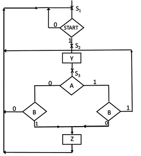
AB’ Å A’B = A Å B
Z = AB’ Å A’B
(a)
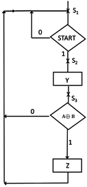
AB’ Å A’B = A Å B
Z = A Å B
(b)
Figure 1. Example 1. The original flowchart and corresponding Boolean equation for output Z is shown in (a). The simplified flowchart and corresponding Boolean equation for output Z is shown in (b).
A’C Å AB’C Å ABC’ = AB Å C
Z = A’C Å AB’C Å ABC’
(a)
![]() A’C Å AB’C Å ABC’ = AB Å CZ = AB Å C(b)
A’C Å AB’C Å ABC’ = AB Å CZ = AB Å C(b)
Figure 2. Example 2. The original flowchart and corresponding Boolean equation for output Z is shown in (a). The simplified flowchart and corresponding Boolean equation for output Z is shown in (b).
![]() ABCD’ Å ABC’D Å AB’D Å A’D = ABC Å DZ = ABCD’ Å ABC’D Å AB’D Å A’D(a)
ABCD’ Å ABC’D Å AB’D Å A’D = ABC Å DZ = ABCD’ Å ABC’D Å AB’D Å A’D(a)![]() ABCD’ Å ABC’D Å AB’D Å A’D = ABC Å DZ = ABC Å D(b)
ABCD’ Å ABC’D Å AB’D Å A’D = ABC Å DZ = ABC Å D(b)
Figure 3. Example 3. The original flowchart and corresponding Boolean equation for output Z is shown in (a). The simplified flowchart and corresponding Boolean equation for output Z is shown in (b).
can be simplified and written as Z = AB Å C in Figure 2(b) from Z = A’C Å AB’C Å ABC’ in Figure 2(a). Figure 3(b) shows Z = ABC Å D. Afterwards, Figure 4(b), Figure 5(b), and Figure 6(b) show the patterns for A Å B Å C, AB Å CD, and AB Å C Å D respectively and they were simplified from patterns in Figure 4(a), Figure 5(a) and Figure 6(a). These simplified patterns are used to minimize the circuit synthesized from flowcharts.
![]() AB’C’ Å ABC Å A’B’C Å A’BC’ = A Å B Å CZ = AB’C’ Å ABC Å A’B’C Å A’BC’(a)
AB’C’ Å ABC Å A’B’C Å A’BC’ = A Å B Å CZ = AB’C’ Å ABC Å A’B’C Å A’BC’(a)![]() AB’C’ Å ABC Å A’B’C Å A’BC’ = A Å B Å CZ = A Å B Å C(b)
AB’C’ Å ABC Å A’B’C Å A’BC’ = A Å B Å CZ = A Å B Å C(b)
Figure 4. Example 4. The original flowchart and corresponding Boolean equation for output Z is shown in (a). The simplified flowchart and corresponding Boolean equation for output Z is shown in (b).
![]() ABCD’ Å ABC’D Å AB’CD Å A’CD = AB Å CDZ = ABCD’ Å ABC’D Å AB’CD Å A’CD(a)
ABCD’ Å ABC’D Å AB’CD Å A’CD = AB Å CDZ = ABCD’ Å ABC’D Å AB’CD Å A’CD(a)![]() ABCD’ Å ABC’D Å AB’CD Å A’CD = AB Å CDZ = AB Å CD(b)
ABCD’ Å ABC’D Å AB’CD Å A’CD = AB Å CDZ = AB Å CD(b)
Figure 5. Example 5. The original flowchart and corresponding Boolean equation for output Z is shown in (a). The simplified flowchart and corresponding Boolean equation for output Z is shown in (b).
![]() ABCD Å ABC’D’ Å AB’CD’ Å AB’C’D Å A’C’D Å A’CD’ = AB Å C Å DZ=ABCDÅ ABC’D’ Å AB’CD’ Å AB’C’D Å A’C’D Å A’CD’(a)
ABCD Å ABC’D’ Å AB’CD’ Å AB’C’D Å A’C’D Å A’CD’ = AB Å C Å DZ=ABCDÅ ABC’D’ Å AB’CD’ Å AB’C’D Å A’C’D Å A’CD’(a)![]() ABCD Å ABC’D’ Å AB’CD’ Å AB’C’D Å A’C’D Å A’CD’ = AB Å C Å DZ = AB Å C Å D(b)
ABCD Å ABC’D’ Å AB’CD’ Å AB’C’D Å A’C’D Å A’CD’ = AB Å C Å DZ = AB Å C Å D(b)
Figure 6. Example 6. The original flowchart and corresponding Boolean equation for output Z is shown in (a). The simplified flowchart and corresponding Boolean equation for output Z is shown in (b).
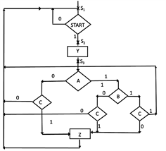
In Figures 1-7, we use rectangles for outputs, diamonds for inputs, and the internal states are denoted with X symbol on the wire with corresponding internal state such as Si (where i = 1, 2, 3, etc.).
![]() (a)
(a)![]() (b)
(b)
Figure 7. Example 7. The original flowchart and corresponding Boolean equation for output Z is shown in (a). The simplified flowchart and corresponding Boolean equation for output Z is shown in (b).
Exclusive or Sum of Product Sums (EOSOPS)
Our synthesis method also allows us to utilize EOSOPS circuits. The PSE gates (Product Sum EXOR gates) [6] that are used in EOSOPS circuits further reduce quantum cost. PSE gates can especially reduce quantum cost in cases where there are many paths that have the OR function. One weakness of the flowchart is that when there are many OR paths, the synthesis results in many equations. EOSOPS allows us to utilize De Morgan’s Law [10] to avoid these many equations and directly represent the function. EOSOPS will be used in our method in all cases with multiple OR paths in the original equation. Figure 7 presents a flowchart along with the associated Boolean equation that can be attained from it, and the reduced Boolean equation. Figure 7(a) shows the initial flowchart and the corresponding Boolean equation for output Z. Figure 7(b) is the optimized flowchart and the reduced Boolean equation for output Z.
We first start by deriving the equation from the flowchart of Figure 7(a):
which results in a quantum cost of 381. However, when we apply De Morgan’s Law to the equation, we reduce it to the following equation:
with quantum cost of 52. The quantum cost is the cost to implement the quantum circuit, which is explained in detail in Section 4 using Maslov cost table [19] .
3. Our Synthesis Method
The method presented uses the Quantum State Machine with External Memory model [9] , as described below.
1) Create a standard flowchart, if necessary, modify its paths to the optimal forms as presented in examples from Section 2.
2) Start traversing the flowchart from “START” and follow each path to every next state and write the Boolean equation for that path. Also, write the equations for the outputs. Since each state is encoded using “one-hot encoding”, each product of literals is disjoint with other products of literals in the next-state equations.
3) Use patterns from the pre-processing stage to reduce the equations, iterate this process if necessary.
4) Realize every product of two literals with standard Toffoli gates.
5) Realize every product of more than two literals with a chain of standard Toffoli gates by adding an ancilla qubit for each additional literal.
6) Using a standard quantum circuit synthesis method [3] [4] [5] [8] [9] [17] , draw the quantum circuit using the results from the previous steps.
7) Mirror the gates on the ancilla qubits and input qubits so they can be reused, if necessary.
3.1. Example 3.1: Quantum State Machine with Classical Memory
This is a small example which shows the implementations of Quantum State Machines with external memory (QSM-CM) [9] . For the equation A = BC, Figure 8 shows the circuit with classical memory. In this particular example, the outputs are the same as the inputs so these quantum outputs are not used. The changed state of the classical memory is used as the deterministic output. Observe here that these machines in general can have both classical (deterministic)
![]()
Figure 8. An example of a very simple QSM-CM with inputs on the left, outputs and excitation function of the memory on the right.
and quantum (superposed) outputs in case when the quantum circuit has superposing gates as for instance the Hadamard gates (not discussed here).
3.2. Example 3.2: Toffoli Reduction
Another goal of our approach is to use only Toffoli, Feynman and quantum inverter (Pauli-X rotation) gates. When we encounter equations derived from the flowchart with generalized Toffoli gates, we first decompose them to more primitive gates using the aforementioned Feynman and Toffoli gates. However, such a method results in a higher number of ancilla qubits. For example, in Figure 9, we show the computation of the product “X = ABCD”. In this case, instead of using 5*5 Toffoli gates, we decomposed the larger generalized Toffoli gates by adding three ancilla qubits and performed simple AND operations using 3*3 Toffoli gates. Figure 9 also illustrates the principle of mirroring which returns input variable and ancilla qubit states to their original values.
4. Examples and Data
Standard methods used by several authors to realize quantum circuits from Boolean functions are based on MMD-like methods [20] [21] [22] , ESOP based methods [23] [24] [25] [26] , or combinations of both. These methods are also suggested to realize permutative automata. We give comparison to the paper of Hawash et al. [17] as just one of the known methods to realize quantum circuits.
4.1. Example 4.1 (Shown as Example 1 in Table 1): A Representative Example from Section 2 Figure 1(a) and Figure 1(b)
This is an example which creates equations based on the flowchart in Figure 1(a) and Figure 1(b). Figure 1(a) is the original flowchart without any Boolean simplification. Figure 10 shows the quantum circuit using Hawash et al. method [17] to implement the flowchart in Figure 1(a). The quantum cost using Hawash et al. method [17] is 72 using Maslov cost table [19] . This circuit has four 3-control Toffoli gates, two 2-control Toffoli gates, two Feynman gates and eight inverters. The following is the quantum cost calculation for this circuit using Maslov cost table [19] .
![]()
Figure 9. This quantum circuit is obtained from reducing the 5*5 Toffoli that would be created from X = ABCD.
![]()
Figure 10. Quantum circuit using Hawash et al. method [17] to implement the flowchart in Figure 1(a).
Quantum cost per 3-control Toffoli gate: 13
Quantum cost per 2-control Toffoli gate: 5
Quantum cost per Feynman gate: 1
Quantum cost per inverter: 1
Total Quantum Cost = 13 × 4 + 5 × 2 + 1 × 2 + 1 × 8 = 72
Figure 1(b) is the simplified flowchart applying Boolean simplification to the original flowchart from Figure 1(a). Figure 11 shows the quantum circuit realizing the flowchart in Figure 1(b) using our new proposed method.
The quantum cost for the circuit in Figure 11 is 26 using Maslov cost table [19] . There are four 2-control Toffoli gates, three Feynman gates and three inverters. The following is the quantum cost calculation for this circuit using Maslov cost table [19] .
Quantum cost per 2-control Toffoli gate: 5.
Quantum cost per Feynman gate: 1.
![]()
Figure 11. Complete realization of the quantum automaton for Example 4.1 implementing the flowchart in Figure 1(b) using our method. It is composed from a permutative quantum circuit, measurement gates and classical D flip-flops. Initialization of qubits is not presented.
Quantum cost per inverter: 1.
Total Quantum Cost = 5 × 4 + 1 × 3 + 1 × 3 = 26.
In Figure 11, we have quantum inputs START, A and B, deterministic binary inputs S1, S2 and S3that come from the classical feedback. There are four ancilla qubits initialized to |0〉. There are quantum output states START, A and B that are not used in this case. Deterministic binary output states Y and Z are taken from output Q of classical D flip-flops. Please observe that output Y is the same as the new state S2+. Deterministic output Z uses a special measurement and D flip-flop to convert from quantum to classical signal. Measurement gates and D flip-flops are used to convert from quantum to classical states.
Our proposed method reduces quantum cost to 26, as compared to Hawash et al. method’s quantum cost of 72.
This is because in the Hawash et al. method, the conversion from irreversible to reversible function increased the width of the circuit by adding ancilla bits [17] , requiring generalized Toffoli gates with more control lines which results in higher quantum cost. Our method does not require reversibility, and hence presents a clear advantage in such cases of synthesizing quantum automata.
In Table 1, we summarized the studied examples. In Table 1, “Example 1 Hawash et al. Method [17] ” corresponds to flowchart in Figure 1(a) and quantum circuit in Figure 10; “Example 1 Our Method” corresponds to flowchart in Figure 1(b) and quantum circuit in Figure 11. Examples 2 - 7 in Table 1 corresponds to flowcharts in Figures 2-7. In Table 1 Examples 2 - 7 “Our Method” column, we documented the quantum circuit cost implementing flowchart in Figures 2(b)-7(b) using our method, similar to what we did in Example 4.1 for Figure 1(b) in this section. In Table 1 Examples 2 - 7 “Hawash et al. Method [17] ” column, we documented the quantum circuit cost implementing flowchart in Figures 2(a)-7(a) using Hawash et al. method [17] , similar to what we did in Example 4.1 for Figure 1(a) in this section.
4.2. Example 4.2 (Shown as Example 8 in Table 1): Create Equations Based on Flowchart, Use Flowchart to Synthesize Quantum Automata
This is an example which creates equations based on a flowchart specification. Figure 12 presents a flowchart that can be utilized to synthesize quantum automata. Figure 13 presents the resultant circuit using our method.
![]()
Figure 13. A Quantum circuit using our method implementing the flowchart in Figure 12.
In Figure 12, we use rectangles for outputs, diamonds for inputs, and the internal states are denoted with X symbol on the wire with corresponding internal state such as ai (where i = 0, 1, etc.).
Below are the equations that are synthesized using our method.
The quantum circuit in Figure 13 has eight 2-control Toffoli gates, four Feynman gates and six inverters. Using Maslov improved quantum cost for n-bit Toffoli gates [19] , the quantum cost per 2-control Toffoli gate is 5, the quantum cost per Feynman gate is 1 and the quantum cost per inverter is 1. Therefore, the quantum cost for circuit in Figure 13 is 50.
We converted the irreversible equations to the format of the method from [17] . The quantum cost using the MMD-like method from [17] was 72 using Maslov cost table [19] , which is higher than our cost. This is because the conversion method from irreversible to reversible function increased the width of the circuit by adding ancilla qubits [17] , requiring generalized Toffoli gates with more control lines which results in higher quantum cost.
Figure 14 is the quantum circuit based on Hawash et al. method from [17] . The circuit in Figure 14 has four 3-control Toffoli gates, two 2-control Toffoli gates, two Feynman gates and eight inverters. Using Maslov cost table [19] , the quantum cost per 3-control Toffoli gate is 13, the quantum cost per 2-control Toffoli gate is 5, the quantum cost per Feynman gate is 1 and the quantum cost per inverter is 1. Therefore, the quantum cost for circuit in Figure 14 is 72.
4.3. Example 4.3 (Shown as Example 9 in Table 1): A Light-Following Robot Example
This is a real-world application of our method. We will go through all steps of
![]()
Figure 14. A Quantum Circuit using Hawash et al. Method [17] implementing the flowchart in Figure 12.
our method. Figure 15 shows the flowchart diagram of a light-following robot.
Based on Figure 15, we obtain the following equations:
Figure 16 presents the synthesized quantum circuit from the above equations using our new method.
Table 1 presents the quantum cost for the circuits synthesized through the proposed method and for those synthesized through the method described in [17] . Results from Table 1 shows that in eight out of the nine studied examples, quantum circuit cost using our proposed method is significantly less than that using Hawash et al. method [17] . The percentage of quantum cost reduction ranges from 31% to 95%. This shows that for many cases, especially those with high numbers of qubits, there are significant advantages of utilizing our proposed method. The novelty of our proposed method is to synthesize Quantum Automata directly from flowcharts using one hot encoding and design the resulting
![]()
Figure 15. Flowchart Diagram of a Light-following Robot.
![]()
Figure 16. A quantum circuit using external memory model obtained from the flowchart of Figure 15.
![]()
Table 1. Quantum Cost for Studied Examples.
quantum circuits using only NOT, CNOT and CCNOT (Toffoli) gates, thus optimize and reduce the quantum circuits cost. Results in Table 1 justify the novelty of our proposed method.
However, there is one case in Table 1 that shows the method described in [17] offers a lower cost. This is related to the trade-off between additional ancilla qubits and lower costs. While quantum costs may decrease by using extra ancilla qubits in the proposed method in some cases, in other cases, often simple, the increase in ancilla qubits increases the quantum cost.
5. Conclusions
We presented a new approach to synthesizing quantum permutative automata by using a standard flowchart as the initial specification. The novelty of our proposed method is to synthesize Quantum Automata directly from flowcharts using one hot encoding and design the resulting quantum circuits using only NOT, CNOT and CCNOT (Toffoli) gates, thus optimize and reduce the quantum circuits cost. Results show that in most of our studied cases, our method reduces quantum cost significantly by up to 95% as compared to Hawash et al. method [17] , this justifies the novelty of our proposed method.
Our approach is restricted only to the “Quantum State Machine with External Memory model” from [4] . In our future work, we will extend this method to other models of quantum automata and specifically to automata with parallelism, superposition and entanglement. We will also emphasize more on practical applications of such automata in the area of robotics.
Our method deals with interesting relationship between one-hot encoding, superposition and entanglement [27] [28] . In our previous work, we presented applications of superposition and entanglement for description of a single mobile robot, for instance, Braitenberg vehicle [29] [30] and humanoid dancing and walking robots [31] . In our forthcoming work, we will present groups of mobile robots that communicate using one-hot codes, superposition and entanglement and are controlled by generalization of quantum automata presented in this paper.
The described method was verified on several example flowcharts which were created as simplified benchmarks based on practical examples. In future work, our method should be compared to previous synthesis methods for quantum automata [4] [5] [9] [12] in terms of quantum cost, LNNM quantum cost, power, speed, testability and decoherence. The method is destined for use in the synthesis of controllers of quantum robots [29] and we plan to compare the influence of decoherence on the same controller with different design styles. In addition, a model of parallel permutative machines can be created in which the machine is in several states at one time. This would be a counterpart of the Parallel Program Graphs (PPG) [32] . We plan to develop a direct synthesis method for PPGs. Other possible work includes transforming Petri Nets to quantum automata. All these methods will include circuit post-processing minimization based on MMDs, ESOPs, EOSOPs, and other quantum circuit minimization methods. We also developed a set of benchmarks that can be used by future authors to compare the costs of various realizations of quantum automata. It is believed that future “quantum hardware compilers” will synthesize quantum systems directly from high level specifications like flowcharts and data flow graphs.