Possible Accidents Scenarios in Zaporizhzhia Nuclear Power Plant ()

1. Introduction
Zaporizhzhia Nuclear Power Plant (ZNPP) is the largest nuclear power plant in Europe and Ukraine. The second nuclear power plant in the world after the Japanese Kashiwazaki-Kariwa NPP, after stopping of which, in 2012, it became the largest operating nuclear power plant in the world. It is located at the Dnepr River on the left bank of the Kakhovka water reservoir. The site is located in the city Energodar, Zaporizhzhia province, Ukraine (see the map on Figure 1). In recent years, the ZNPP generates about 50% of all electricity produced by nuclear power plants in Ukraine, and almost 21% of the total electricity generation in the country. 10 million residents of Ukraine live and work thanks to the electricity of Zaporizhzhia nuclear power plant. The State Enterprise National Energy Generating Company (ENERGOATOM) is the operator of ZNPP [1] .
The council of USSR ministers decided to build ZNPP in 1978. First stage technical design, consisting of 4 units with total power of 4 GW was approved in 1980, and the first unit was commissioned in 1984. The second, third and fourth units were commissioned in 1985, 1986 and 1987 respectively. Meanwhile, the second stage, involving two additional power units with similar reactors, was proposed in 1988; the fifth and sixth units were commissioned in 1989 and 1995 respectively [1] .
An overview of the Zaporizhzhia NPP site is given in Figure 2, where one can distinguish the 6 units reactor and all other ZNPP facilities [2] .
ZNPP is a six-unit nuclear power plant. Each generating unit consists of VVER-1000/V-320 reactor, K-1000-60.1500-2 steam turbine and TWW-1000-4 generator (see Figure 3).
VVER-1000/V-320 is 1 GW nuclear power plant with pressurized water reactor designed in former Soviet Union. The primary circuit of VVER-1000/V-320 unit consists of reactor and four identical primary circuit loops of Dn 850 mm with steam generators (S/G) PGV-1000M, reactor coolant pumps (RCP) of GCN-195M type and pressurizer (PZR).
The primary system transfers the heat from the fuel to the steam generator, where the secondary system begins. The steam formed in the steam generator is transferred to the main turbine generator, where is converted into electricity.
The steam is routed to the high pressure (HP) main turbine. After passing through the high-pressure turbine, the steam is piped to the moisture separator/ reheaters (MSRs). In the MSRs, the steam is dried with moisture separators and reheated using other steam as a heat source. From the MSRs, the steam goes to the low-pressure turbines. After passing through the low-pressure (LP) turbine,
![]()
Figure 1. Map of Ukraine and Russia and the ZNPP location.
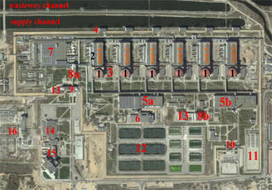
1―reactor vessel, 2―turbine building, 3―diesel generator, 4― unit pumping plant, 5―radwaste treatment buildings, 6―solid radwaste storage, 7―additional buildings, 8―laboratory and service structures, 9―administration buildings and check gate 1, 10―check gate 2, 11―dry spent fuel storage facility, 12― spray ponds, 13―canteen, 14―full scope simulator, 15―training center, 16―750 kV switchyard.
Figure 2. The Zaporizhzhia NPP site [2] .
the steam is routed to the main condenser. Cool water, flowing through the tubes in the condenser, removes excess heat from the steam, which allows the steam to condense. The water is then pumped back by main feed pump to the steam generator for reuse. In order for the primary and secondary systems to perform their functions, there are approximately one hundred support systems. In addition, for emergencies, there are dedicated systems to mitigate the consequences of accidents [3] .
The electricity generated in ZNPP is supplied to the Ukrainian grid through four 750 kV over headtransmission lines. One of the 750 kV lines runs northwards across the Kakhovka Reservoir and on to the Dniprovskasubstation just south of Vilnohirsk in Dnipropetrovsk Oblast. The last-built of the750 kV lines runs 186 km south-westward to the Kakhovska substation just west of Nova-Kakhovka and was commissioned in 2021. Three 330 kV back-up lines, connected to a thermal power plant, remain on standby during normal operation, but can be used to deliver the electricity generated at Zaporizhzhia to the grid. In the event of complete loss of offsite power, each reactor has three back-up diesel generators. Nuclear power plants require back-up electricity supplies to provide cooling for the removal of decay heat produced by shutdown reactors, and to maintain services (e.g. systems control, lighting, communication, ventilation) to the site [4] .
2. Problem Formulation
On 2 March, at the meeting of the IAEA’s Board of Governors, IAEA Director General, outlined seven indispensable pillarsfor ensuring nuclear safety and security in relation to the situation in Ukraine [6] :
1―The physical integrity of the facilities―whether it is the reactors, fuel ponds or radioactive waste stores―must be maintained.
2―All safety and security systems and equipment must be fully functional at all times.
3―The operating staff must be able to fulfill their safety and security duties and have the capacity to make decisions free of undue pressure.
4―There must be secure off-site power supply from the grid for all nuclear sites.
5―There must be uninterrupted logistical supply chains and transportation to and from the sites.
6―There must be effective on-site and off-site radiation monitoring systems and emergency preparedness and response measures.
7―There must be reliable communications with the regulator and others.
On 29 August, the IAEA Support and Assistance Mission to Zaporizhzhia (ISAMZ), which comprised a high-level delegation and technical team, arrived in Ukraine to assess the current situation related to nuclear safety and security at the ZNPP [7] .
ISAMZ main attention have been paid to physical damages due to the shelling, furthermore the IAEA team confirmed that the sites spent fuel pools operated normally.
In Table 1, we summarized the main events, which have been occurred at the ZNPP during the military conflict between Russian Federation and Ukraine (for more information about the implications of the Russian-Ukrainian conflict for nuclear safety and security since 2014, see [8] ).
![]()
Table 1. Chronology of events at the ZNPP.
The report of IAEA Director General contains 7 recommendations that should be implemented to avoid a nuclear accident at the ZNPP with serious consequences to the plant site and surrounding areas (for details see [7] [9] ).
If we exclude military operations that may lead to direct external damages to the station buildings and equipment, there are many other damages that must be taken into account, the most important of which are:
Interruption of the electrical power supply, which may lead to the failure of the reactor circulation cooling pumps and cooling equipment in spent fuel pools, ventilation systems, drainage systems and other equipment in the plant.
Breakdown of diesel generators and batteries reserve, which are used for in-house needs.
Of course, shutting the reactors down offers little immediate protection, because the spent nuclear fuel from the reactors is stored in cooling pools for 4 - 5 years until the residual energy and radioactivity decrease. It is then transported to Dry Spent-Fuel Storage Facility (DSFSF). ZNPP includes a DSFSF with a 50-year service life, which has been developed in July 2001, the spent-fuel ventilated dry storage casks are manufactured by Sierra Nuclear Corporation (SNC) [2] . The DSFSF of ZNPP is an open storage facility, the concrete containers (casks) stand outdoors surrounded by a wall to avoid radiation impact on ZNPP staff, population and environment (see Figure 2(11)).
The radioactive decay continues for decades after reactor shutdown, the typical radiotoxic elements of spent fuel water are: Sr-90, Cs-137, Am-243, Pu-239, U-238, Tc-99… The issue of radiotoxicity is very important to be sure that the spent fuel pool design safely protects the workers of power plant [10] .
Residual fission heating in storage pools is generated by the decay of radioactive fission products after reactor shutdown, the decay heat is in effect the results of the beta and gamma decays.
So, without constant cooling, the temperature of the water in the cooling pools will begin to rise, and after some time may lead to boiling and then evaporation of water; and under some conditions, depending on various possible scenarios, dangerous nuclear accidents can be occurred in the spent fuel pools (SFP).
In the following paragraphs we will discuss the most possible physicochemical processes, which may lead to such dangerous scenarios.
Prior to 2011, in literature, there were relatively little information about the emergency regimes in SFPs. Interest in this problem increased after the accident at the Fukushima Daiichi NPP. The incident in Japan launched a whole series of works devoted to the analysis of the stability of power units and spent nuclear fuel storage facilities. Published works about VVERs spent fuel pools demonstrate the danger of water boiling in the pools with a further decrease of its level and exposure of spent fuel assemblies (SFAs) with overheating of the claddings, up to their melting and destruction [18] .
According to the current regulatory documents [19] [20] [21] , one can distinguish two scenarios, which can lead to heating of spent fuel in storage pools:
1) Complete desiccation of SFPs, caused by destruction of pools’ sections,
2) Full and long shutdown of power plant.
In the case of complete desiccation, the main consequences result in cooling system interruption with fuel heating in the pools and destruction of fuel element shells at critical temperatures. In this case, radiation dose can increase in the SFPs hall and activity run-away.
Complete and long-term shutdown of the plant is not considered as a separate Beyond Design Basis Accident (BDBA) at SFPs, although it is partially considered as a Design Basis Accident (DBA). The raison is the restrictions posed by the design limits or the assumption of the success of taking operational measures to prevent the transition of an emergency event to the stage of a BDB or severe accident. Thus, in the case of complete blackout of cooling system, it is assumed that the power supply can be restored during 6 - 8 hours [18] .
The accident with a complete and long-term shutdown of SFPs is accompanied by radiolytic hydrogen release and the heating of the water pool. The accident scenario is determined by many factors: SFAs energy release, their quantity, the influence of water evaporation process from the surface of the pools. The released hydrogencan accumulate in high concentration under the slotted cover and in the pool hall, which can lead to explosion.
It should be mentioned that, there are 3 mechanisms for hydrogen formation:
Water radiolysis reaction,
Hydrogen solubility decrease at high temperature,
Steam-zirconium reaction.
In fact, the lack of attention to the temperature regimes was mainly related to the small amount of energy released by spent fuel, so it was considered that the probability of having the necessary conditions for such accidents is very low. But this approach has been changed after Fukushima Daiichi accident; hence in 2014, Western European Nuclear Regulators’ Association (WENRA) published a revised version of the Safety Reference Levels (RLs) to take into account lessons learned from Fukushima Daiichi accident (see [22] ).
Furthermore, the accident analysis are usually based on Probabilistic Safety Analysis (PSA). Even though the calculated probability of severe accidents is very low, the consequences caused by these accidents are potentially enormous. So, the conclusion of State Nuclear Regulatory Inspectorate of Ukraine (SNRIU) that the units are operating safely with an acceptable level of risk cannot be agreed on the basis of the available information [2] . Additional information on internal hazards is provided in IAEA Safety Standards NS-G-1.7 and NS-G-1.11 (see [23] [24] ).
Thus, the issue of the safety of SFPs during long-term heating is fundamental from the point of view of the possibility of realizing the conditions of DBAs and BDBAs. Schematically, possible consequences of SFPs long-term heating are presented in Figure 4.
With increasing of temperature, the water in the SFPs start boiling and then
![]()
Figure 4. Scheme of possible events in SFPs.
evaporating; as consequence, the water level in spaces between canisters of SFAs, which can lead to conditions suitable for nuclear chain reaction (NCR) ignition. Also, with the increasing of water temperature, the solubility of hydrogen in water decreases and it is possible to increase its output into the atmosphere. When water evaporates, radioactive gases dissolved in the pool water are released together with steam. In the case of long desiccation, it is possible to increase the temperature to high values, which will decrease carrying capacity of the metal structures, racks and concrete walls, and, as a result, spent fuels assemblies’ canisters falling, which in turn can lead to an NCR. As well as, at high temperature cladding of SFAs can break out under the internal pressure of the gases. Thus, all the above-mentioned series of events may lead to an uncontrolled activity run-away.
The main purpose of this article is to analysis the residual heat generation after shutdown of reactors. So, we have estimated the time required for water to start boiling and the time required for the uncovering of fuel assemblies in various sections of ZNPP spent fuel pools after full shutdown of power plant reactor units, and, basing on obtained data, we will discuss the possible events which can take place in ZNPP.
3. Theoretical Model
The proper calculation of decay heat is necessary for both postulated accidents and normal spent fuel repository safety analysis. There were many attempts and approaches to calculate decay heat of fission products.
Wigner and Way considered fission products as a sort statistical assembly, and, using empirical relations, they could relate the decay heat generated by fuel assemblies to their initial power by a formula of the type [25] :
(1)
where:
is the time since the shutdown of the reactor,
is the operational time of the fuel in the reactor,
is decay power at the time t after shutdown,
is the reactor power level,
are constants.
Basing on this approach, one can use the following expression [26] :
(2)
where t and T0 in days.
In [25] , some modifications had been done to formula (2) to fil experimental data over the entire available range, which yielded to:
(3)
As more general estimation of decay heat is based on the American Nuclear Society standard equation [27] :
(4)
where the constant a and b are defined in Table 2.
Summing exponential decaying terms of various individual isotopes, some authors have derived the following expression (see [26] ):
(5)
The values of
are presented in Table 3.
Notice that,
in Equations (3)-(5) should be in seconds.
![]()
Table 2. Values of constants a, b for Equation (4).
![]()
Table 3. Values of constants
for Equation (5).
In Figure 5, we have represented the values of ratio P/P0 as function of time. One can see that the data of various equations are very close, so we have calculated the average, which can be very well approximated by a power expression, with good regression coefficient (R2).
(6)
Now, to calculate the water boiling time tb, one can find the total amount of energy required to saturate the entire pool section.
(7)
where:
is density of water,
V volume of water in the pool section,
heat capacity of water at constant pressure,
temperature of boiling for water,
initial temperature of water in the pools.
We can calculate the amount of energy released by the spent fuel at every moment by integration the Equation (6):
(8)
![]()
Figure 5. Values of P/P0 using various approaches as function time.
So, putting
in (8) and using (7), one can easily find:
(9)
To evaluate the critical time when enough energy has been produced to boil off all the water above the fuel assembly, can be found using the following expression:
(10)
where:
is the specific heat of vaporization for water,
S is the surface of pool section,
is the initial height of water above SFAs racks in the pool section,
is the height of SFAs racks in the pool section,
is the time to boil off all the water above SFAs racks.
Using the Equation (5), one can easily find:
(11)
It should be mentioned here that the
is time for complete desiccation of SFAs after the boiling of water.
4. Results and Discussion
The ZNPP spent fuel pools consist of sections TG21B01, TG21B02, TG21B03 (abbr. B01, B02, B03). The “wet” refueling pools (WRP) consists of the total sections of the TG21B05, TG21B06 (abbr. B05, B06) and the reactor pit. In the Figure 6(a) and Figure 6(b), we have represented the geometrical dimensions of all SFPsand WRPs and reactor pit [28] .
SFPs sections walls are covered with two layers of sheet steel, the inner layer is made of carbon steel with thickness 8mm, the outer layer is of 08X18N10T steel with thickness mm as well, the gap between them is 8 mm (all information all the properties of ZNPP SFPs, WRPs, reactor pit and cooling system are provided in technical manual [28] ).
In all our calculations, we have suggested that the operational time of the fuel in the reactor is 5 years, i.e. T0 = 5 y, and it is a standard time for VVER reactors. Here, it must be pointed out that we don’t have any information about the real operation time of nuclear fuels in ZNPP reactors.
The properties water we need to achieve calculations are summarized in the Table 4.
The geometrical properties of SFPs and SFAs racks are presented in the Table 5.
In our calculations, we will be restricted on the sections B01, B02, B03; because, in our opinion, it is enough to bringing out the dimensions of threat.
In the sections B01 and B03, at level 28.83 m, the volumes of water in all units
![]() (a)
(a)![]() (b)
(b)
Figure 6. Spent fuel pools geometry [28] .
![]()
Table 4. Properties of water [28] [29] .
![]()
Table 5. Properties of spent fuel pools [28] .
are very close, so we have used an average value 212 m3; but at the level 36.20 m we have used an average value 404 m3 for B01 + B03. Also, in the section B02 at level 28.83 m, we have used an average value for volume of water 98 m3; while B02 at level 36.20 m, we have used an average volume 190 m3.
Using the equations (9) and (11), it is easily to find the values of boiling time and boiling-off time, for various SFPs sections, as function of reactor initial power, the results are presented in Figure 7 and Figure 8.
From Figure 7 and Figure 8, in the case of complete blackout of SPFs cooling systems, it is obvious that the water in SFPs sections can begin to boilafter 1 - 45 hours, depending on the section, even if the unit reactors were operating at very low power (50 - 100 MW), and the boiling-off time is about few hours to few days.
In the case of high powers, situation will be mor dangerous, because the boiling time can be less than an hour in some sections, and the boiling-off time is about few hours.
![]()
Figure 7. Boiling time in the SFPs sections.
![]()
Figure 8. Boiling-off time in the SFPs sections.
Indeed, in our calculations, we didn’t take into account any heat losses by various heat transfer mechanisms, but we considered all amount of energy decay go into heating of the water. Nonetheless, we believe that it is well justified, because, these losses are not very high and don’t significantly influence these times.
However, in addition to the energy generated by the decay of radioactive fission products, there are other sources of energy from the oxidation of fuel assemblies’ metals (zirconium, chromium, iron and nickel) in water, steam and air, and all these oxidation reactions are exothermic, and in some cases and conditions can release an important amount of heat.
In fact, zirconium chemically interacts with water and water vapor in an oxidation reaction, releasing hydrogen gas and some heat [30] :
where
is the heat of zirconium oxidation reaction in water.
The main relations for zirconium oxidation reaction with water can be found in the works of Baker & Just (see [30] ), so, the following rate law was deduced:
(12)
where: W is milligrams of zirconium reacted per sq cm of surface area, t is time in seconds, R is the gas constant and T is the temperature.
Chemical heat production could exceed the nuclear heat generation during a destructive nuclear transient. According to Osipov’s calculations, this heat can reach few MW at high temperature (see [18] ).
Moreover, Zirconium can be oxidized in air as well [31] :
where
is the heat of zirconium oxidation reaction in air. Notice that
.
In addition to zirconium oxidation reactions, zirconium nitridation reaction (formation of zirconium nitridesZrN) can also take place at high temperatures 500˚C - 1800˚C. This reaction is also exothermic and the released energy is about 2930 kJ/kg.
Furthermore, at high temperatures the metals entered in stainless steel, i.e. chromium, iron and nickel, may be oxidized but the released heat is very small, about, Q = 150 - 200 kJ/mole, comparing to zirconium oxidation and nitridation.
So, in order to draw a complete picture about temperature regimes in SFPs and reactor, we should take into consideration all chemically released energies. Evidently, these additional sources of energies would decrease the boiling and boiling-off times of water, and as a result increase the probability of dangerous accidents.
As we mentioned above, hydrogen generation is considered one of the most dangerous factors in SFPs. Hydrogen generated by the reaction could give rise to a pressure surge and might subsequently react explosively with oxygen air [30] .
Basing on some simulation programs, in [32] [33] authors had demonstrated that the amount of generated hydrogen is not dependent of the spent fuel heat decay. In other words, hydrogen generation can take place even at low energy release of spent fuel. Zirconium oxidation reaction contribution is about 34.7% - 50.3% of total amount of generated hydrogen, and the iron oxidation contributes to about 11.7% - 26.6%. Hydrogen generation starts in a few hours and the rate is about 19 g/s.
So, in the case of severe accident, as in Three Mile Island-Unit 2 Accident (TMI-2 accident), the hydrogen distributed between gas-steam bubble and the gas, which escaped to the reactor building. After some time, the concentration of hydrogen in a region of the reactor building became high enough to support combustion and ignited. The hydrogen gas bubble in the top of the reactor vessel was gradually removed from reactor coolant system during the first several days by continuing let-down of coolant to the makeup tank, and by spraying coolant into pressurizer and then venting the pressurizer (see [34] ).
The main challenge in accidents scenario analysis, in general, is that the number of possible scenarios grows very rapidly with the number of parameters (events) and their outcomes. This is because for every combination of outcomes of these parameters (events), there exist a distinct scenario that could be generated. Thus, if there are 10 parameters with 3 possible outcomes for each, for example, the total number of possible scenarios which can be defined is 310 = 59 049 [35] .
In the case of ZNPP, on one hand, there exist too many parameters, and, on the other hand, due to the lack of information, we don’t have a real picture about ZNPP. If we restrict our investigation to scenarios directly related to the SFPs cooling system, we can define 7 parameters (i.e. external power supplying, diesel generators operation status, water boiling, water evaporation, metals’ oxidation, hydrogen generation, NCR) with 2 possible outcomes (yes or no), the number of possible accidents scenarios is 128.
Thus, at the moment, it is very difficult to estimate the probability for every event or the value of every parameter, and, consequently, to construct a realistic accidents scenarios tree. In this regard, it should be mentioned that, dangerous events analysis should be carried out regardless of the probability of their occurrence (see [20] ).
Our results demonstrate that the events related to SFPs temperature regimes can be a starting point of dangerous accidents, and the probability of such scenarios is not negligible; and this is the main objective of this article.
Furthermore, to provide a full analysis of possible accidents’ scenarios relating to an assessment of the possible consequences of hazards other than shelling and missiles in ZNPP, many other factors should be taken into consideration; of these factors we can mention, for example: collapse of structures, pipes’ failure and whip, jet effects, flooding, fires, operating staff, safety and security equipment…
Finally, we think that units’ launching after long shutdown represents a dangerous stage, because it is very difficult to check the state of the art of ZNPP equipment.
5. Conclusions
Basing on various approaches, we have calculated the decay heat generated by fuel assemblies after reactor shutdown. Using these data and a simplified model, we have estimated the water boiling and boiling-off times in ZNPP spent fuel pool sections for 6 units. We also have pointed out the threats related to hydrogen generation due to the zirconium oxidation in water. The present results confirm that the probability of severe accidents after complete blackout of cooling systems in SFPs is not negligible, and this possibility wasn’t taken into consideration in the IAEA reports.
In our calculations model, we have considered that all decay heat is going into heat of the water in the SFPs and neglected other heat losses. And also, we didn’t take in account the chemically released energies from the oxidation and nitridation reactions of the SFA and SFPs racks metals. Of course, these are very interesting research questions, and, to treat them one need more sophisticated model, and this will be the subject of future works.