1. Preamble
The concept of computational emancipation of problem domain has been coined in the paper [1]. It denotes the process of a problem domain formalization by means of a domain ontology. The goal was the development of software tools that would simplify computer usage in problem solving process and would allow computer users to computationally emancipate their problem domains, thus eliminating the fear of jobless society by automation. But these ideas did not reach the targeted computer community. During the last 5 years the usage of ontology as a computation mechanism in software development has taken a different path [2] which does not help making computer usage simpler. In addition, some of the articles in the viewpoint section of Communications of the ACM show that confusion about what is and what is not computer science deepens, and the misunderstanding of artificial intelligence threatens to derail further developments of computer usage as a problem solving tool. Therefore I decided to republish this paper thus hoping that its main ideas will reach computer community. The basis of these ideas is the assumption that computer is a brain tool and computer science is simple the science of computer use during problem solving process. Problem solving is characteristic to all human domains of activity and the human brain is the human organ in charge of performing it. Hence, the computer needs to be seen as a brain assistant and natural language should be the language a problem solver uses. In addition, any problem solver should be able to employ the computer during problem solving process according to her computation needs. That is, because all humans solve problems, all humans use the natural language of their problems domains and consequently all humans should be able to use their brain assistant, that is the computer, as a problem solving tool. Computational emancipation of problem domain, that is using the problem domain ontology, enables these desiderata because:
1) All concepts of problem domain can be stored in a file whose records are both concept terms and term meanings.
2) Computational emancipation mimics the human learning process, where knowledge is stored, both by terms and by meanings in a file, exactly like natural learning stores concepts by terms and by meaning in the brain.
3) Problem domain ontology allows us to disambiguate natural language and thus to develop software tools that make computer use as easy as the usage of any other tool developed by humans to strengthen them during problem solving activity.
4) Hence, computational emancipation is simple the process of natural learning using current computer technology.
This paper presents the methodology sketched in [3] towards this endeavor and therefore deserves to be largely known.
2. Introduction
The problem we address in this paper is the integration of the computer as a brain assistant within the human problem solving process. Original computers have not been developed as problem solving tools. Rather, computers were developed as number crunching tools to be used by mathematicians and engineers. The computer based problem solving methodology provided by the creators of the original computer consists of:
• Formulate the problem;
• Develop a solution algorithm;
• Encode the algorithm and its data into a program in the language of the computer;
• Let the computer execute the program;
• Decode the result and extract the solution of your problem.
This problem solving methodology offers computer programming as an “one-size-fits-all” pattern for computer use as a problem solving tool, independent of the problem domain. Therefore one may say that this paradigm of computer use integrates the problem solving process within the computer.
Successes of computer use during problem solving process have evolved software tools at the level of information processing services [4]. Moreover, currently the networking technology allows software tools to be exchanged as standalone pieces of composeable tools called Web Services (WS). A new problem solving paradigm based on WS-s emerges, where computer based problem solving process is split between problem domain expert and computer expert according to their expertise as follows:
• Domain expert formulates the problem and the solution algorithm in terms of problem domain concepts;
• Computer expert implements software tools and domain concepts as web services using computer languages;
• Computer user acquires and manipulates WS-s in order to solve her problems.
The architecture of the problem solving software resulted depends upon the problem domain and evolves as a Service Oriented Architecture (SOA). The computer platform that runs it is transparent to the problem solver. Therefore, one may say that with this problem solving methodology computer is integrated within the human problem solving process. The problems raised by the interoperability of WS-s components of SOA-s are resolved using new standards. XML technology led to the development of three main standards that are used for the implementation of SOA-s:
1) Standard (Small) Object Access Protocol (SOAP), a standard that allows applications to invoke WS-s irrespective of the computer architecture on which they run.
2) Web Service Description Language (WSDL), a standard that allows software developers to describe WS-s such that they can be discovered and used by other developers.
3) Universal Description, Discovery, and Integration (UDDI), a standard registry that allows software developers to advertise, sell, and buy WS-s.
These standards transform computer based problem solving process into a computer business where the exchange unit is the WS. Unfortunately this computer business is not targeted to the computer user. By the contrary, in addition to the language of the software tools, now computer user needs also to learn the intricacies of Web Programming, the language of the WS-s and SOA-s.
The recent hype about Cloud Computing (CC) promises to bring computers as problem solving tools to the masses. However, so far the main research on CC [5] concerns mostly cloud infrastructure management, expressed in terms of Virtual Machines (VM-s) populating the cloud at a given time. But current VM-s in the cloud context are abstractions of computer architectures not abstractions of problem domains. Therefore CC is addressed to computer experts not to problem domain experts. Moreover, the goal of CC is stated mostly in terms of computer resource optimization and efficiency, not in terms of how computer use can be addressed to masses. We believe that populating the cloud with domain dedicated virtual machines CC becomes a problem solving tool dedicated to masses.
3. Problem Solving Process
Problem and problem solving are among the few concepts computer scientists use without defining them, under the assumption that everybody understands them a priori. But for different domains of activity problem and problem solving may mean different things. For example, for a high-school student solving the equation
means the development of the formula
which when fed with the coefficients
of the equation evaluates to the numbers
that satisfy the equality
. On the other hand, for a computer expert this may mean the development of a program that inputs the numbers
and evaluates the expression
for all
, where
and
are minimum and maximum real numbers representable in machine memory, and outputs those x for which the value of
is zero. Teaching students the art of problem solving, Polya [6] has defined the concepts of a problem and problem solving as follows:
To have a problem means to search consciously for some action appropriate to attain a given aim. To solve a problem means to find such an action.
Notice that hidden here are three things: unknown, action, purpose. These concepts are independent of problem domain, therefore Polya’s definition is robust. Polya’s problem solving process involves the operations: identify the unknown, find the action that leads from the given data to the discovery of unknown, and check that the unknown thus found satisfies the purpose, i.e., satisfies the condition that characterizes the problem. Unknown, action, and purpose are natural language terms used to formulate and solve problems in any problem domain. In any scientific domain the natural language ambiguities in problem formulation and solution algorithm development are resolved by the domain context. That is, for mathematician an unknown may denote a mathematical abstraction while for a chemist it may denote a concrete chemical substance; the actions performed by the mathematician while developing a solution algorithm perform operations with mathematical abstractions while the actions performed by the chemist are operations with concrete physical instruments and chemical substances. Scientists solving problems manipulate the objects of their sciences whose meanings are different though their natural language notations may be the same. That is, though the natural language is infinite through the infinity of the discourse it manipulates, in any given domain the language used by the domain expert is unambiguous and is finitely generated by the mechanism of knowledge acquisition and use. Consequently, the problem solving process proposed by Polya is linguistically unambiguous and domain independent. Focusing on mathematical objects, Polya formulates it as the four steps problem solving methodology:
1) Formalize the problem;
2) Develop a plan (an algorithm) to solve the problem;
3) Perform the algorithm on the data characterizing the problem;
4) Validate the solution by checking the validity of problem conditions.
The requirement to formalize the problem means to express the three characteristic concepts components of the problem, unknown, condition, data, as mathematical objects. The result of “problem formalization” step depends upon mathematical knowledge and problem understanding. The requirement to develop a solution algorithm asks the problem solver to discover a sequence of well-coordinated operations which when applied to the data characterizing the problem leads to the values of the requested unknowns. The requirement to perform the algorithm asks the problem solver to actually execute the operations involved in the algorithm using her brain as a tool. This means to instantiate the problem by appropriate data, conditions, and unknown and to execute the operations defining the algorithm on the problem instance thus obtained. The requirement to validate the solution means to shows that conditions characterizing the problem are satisfied by the solution discovered by the algorithm execution.
Computers evolved from tools that can help performing numerical operations to tools that can perform any kind of well-defined operation. Hence, computer can be used to help with algorithm execution irrespective of the problem and problem solving algorithm. To straighten the mechanism used by computers to perform operations during an algorithm execution, we give below an algebraic specification of a computer [7]:

The essential part is the action Program Execution Loop (PEL) composed of the functions Perform () and Next (). Perform () takes as the argument a control register called Program Counter (PC) and evaluates the operation encoded as its contents; Next (PC) determines the operation of the algorithm to be performed next. Computer Based Problem Solving Process (CBPSP) uses Polya methodology where problem solving algorithm is performed by a computer. This requires that problem characteristic components unknown, data, condition, as well as problem solving algorithm, be encoded in computer memory. The process of this encoding has been called the computer programming. In addition, a mechanism for activating the computer on a given program and for controlling computer’s actions during program execution, must also be provided. This has been called the program execution.
Computer programming and program execution are tedious and error prone tasks, and they require problem solver to be a computer expert. So, to make computers usable by the human, an evolving collection of programming tools have been developed as the system software. According to services provided for program development and execution, system software tools can be classified as translators and operators. Translators allow programmers to use high level mnemonic terms for machine operations during programming. Operators manipulate computer resources (memory, processor, devices, control, information) and events (interrupts and exceptions) that occur during program execution. But it doesn’t matter the abstraction level of the terms used to denote computer resources, events, and system software tools, these terms represent computer elements and computer computation concepts. Software tools are not problem domain concepts. Therefore CBPSP actually embeds problem solving process into the computer language, irrespective of the problem it solves. To bring computers to masses it means to reverse this process, i.e., to embed the computer into the problem solving process. This is achievable by letting computer user employ the computer during the algorithm evaluation as a brain assistant that performs operations required by the control flow of the algorithm evaluation. Current computer technology makes this task feasible by developing software tools that allow domain expert and computer expert to share the problem solving process according to their domains of expertise, as follows:
• Domain expert formulates problems and develops solution algorithms using the problem domain logic;
• Computer expert develops software tools and provides them to computer users as web service;
• Computer network experts develop tools that allow problem solvers to ask computer networks to perform the tasks involved in their problem solving processes.
Irrespective of their expertise, all of them can use the computer as a brain assistant during their activity. The new software tools required by this computer based problem solving methodology are:
• The Domain Algorithmic Language (DAL), a computational language to be used by the problem solver to express problem solving algorithms.
• Computational Emancipation of the Application Domain (CEAD), which provides a data-representation of the problem domain that automates algorithm evaluation using a Domain Dedicated Virtual Machine (DDVM);
• The DAL System that implements the DDVM (in the cloud) and offers computer services to the computer user by subscription, without asking computer knowledge in order to consume these services.
In this paper we illustrate these tools using the implementation of NLD System taking the Arithmetic as the problem domain [8].
4. Domain Algorithmic Language
Polya’s problem solving methodology is centered around problem formalization and problem solving algorithm development, using problem domain concepts. This is easily done for mathematical problems because mathematical well defined concepts are implicitly formalized. But for other problem domains, problem formalization and algorithm development may not be so obvious. However, whatever problem domain may be, problem formalization means define problem concepts and methods in terms of well-understood concepts and methods. Using a mathematical say, “one cannot expect to be able to solve a problem one does not understand”. Our conjecture here is that solvable problems of any problem domain are expressible in terms of a finite number of well defined concepts. This is trivially true for the common sense problems raised by the usual real-life. A formal proof of this conjecture can actually be sought using decidability theory [9].
We assume further that for a problem solver, the problem domain consists of a set of well defined domain characteristic concepts, and is modeled by a tree as shown in Figure 1.
The Primitive leaves of the modeling tree represent domain characteristic concepts that are common to all domain experts. Primitive data are expressed by the concepts of variable and value. Primitive actions are expressed by the simple phrases of the form:
,
where
and
are data or actions (as appropriate), and
and
are operations to perform or predicates to check, expressed by the common linguistic jargon of the domain. The Defined leaves of the modeling tree represent concepts created by problem solving and are specific to the problem solver. However, the mechanisms used to define new data and action concepts during problem solving are specific to the domain. We assume here that data definition mechanisms are formalized by mathematical concepts of pair, vector, table, list, set, function. Linguistic expressions of these definitions are domain characteristic, are tailored to the problem and, as appropriate, are formulated by the problem solver. The action definition mechanisms are formalized by mathematical rules that define the action-composition operations by expression-well-formation, concatenation, choice, iteration. The linguistic expressions of these definitions are domain specific phrases. Figure 2 shows the example of tree modeling of arithmetic.
![]()
Figure 1. Tree modeling of a problem domain.
This domain modeling implies that the solution (algorithm) of any problem domain defines a new characteristic concept of that problem domain. Consequently, by problem solving, a problem domain becomes a potentially infinite collection of concepts usable to solve other potential problems of that domain. Problem solutions (algorithms) are expressed in terms of concepts and operations characteristic to the domain. These are actually valid expressions in the natural language of the problem solvers, which are understood by all domain experts because these expressions use only concepts familiar to the domain experts.
For example, for a high-school student learning arithmetic, the problem domain may be characterized by the set I of integer numbers with the operations
,
,
. Then, solving the equation
,
,
means finding
such that
. Using the properties of equality, the problem solver develops the formula
. But one can easily observe that b/a is not always an integer. Therefore, problem solver concludes that
is not always solvable over the set of integers. However, if she extends I to R, the set of all real numbers, then the equation
is solvable and its solution is
. Since division by zero is not defined, the problem solver requires the condition
.Thus, by solving the problem a new well-defined concept, the set R of real numbers, has been developed and problem domain was enlarged with the new concept, Figure 2.
The specification of the Domain Algorithmic Language (DAL) can be done using a vocabulary that contains language terms used for few characteristic concepts of the domain, and very simple rules for sentence formation. The potential ambiguity of these terms is eliminated by their meaning in the domain. In other words, though phrases containing these terms may be ambiguous as natural language expressions, these ambiguities are transparent for a domain expert. That is, for a problem domain D, DAL (D) is the language spoken by an expert of the domain D.
The problem solving process expands the vocabulary of DAL (D) with the terms used to name problem solutions. In addition, problem solution expressions (algorithms) expand the sentence formation rules with the rules provided by the solution expression. This mimics the natural learning process that characterizes the problem domain. We should observe here the difference between computer languages and DAL. Computer languages have a fixed vocabulary (lexicon) and a fixed set of algorithm well formation rules. DAL’s vocabulary (lexicon) and the concept terms well formation rules evolves dynamically with the domain learning process.
Formally DAL may be specified using a pattern similar to the pattern used to specify computer languages, which consists of given a finite set of BNF rules specifying terms denoting domain characteristic concepts and few simple BNF rules for statement formation. Further, DAL specification mechanism allows both its vocabulary and formation rules to grow dynamically with domain learning process. We call this the process of DAL’s evolution. Since DAL terms and algorithms are natural language concepts (though they may have machine representations) domain experts can freely reuse them as components of the new concepts and solution algorithms developed during problem solving process, while preserving the unambiguity of DAL.
Grammatically, the initial terms of the DAL vocabulary would be categorized as nouns, verbs, adjectives, and adverbs. Here we choose the statement formation rules to fit the Resource Description Framework (RDF) used by the Semantic Web [10] [11],
,
, where
,
,
,
are elements of the DAL vocabulary. But for any problem domain these rules can be chosen by domain expert collaborating with computer expert to fit the advances of their domain evolution. Of course, solution algorithms developed by the problem solving process are seen as statement formation rules expressed in terms of the already defined statement formation rules. The evolving DAL specification defined above could be best illustrated by any of the formal systems provided by the axiomatic specification of set theory [12].
Computational nature of DAL is obtained by DAL’s semantics specification using a description logic [13] whose model is defined as follows:
• Implement every concept C of the DAL terminology as a web service WS (C). Let URI (C) be the URL of the WS (C).
• Implement formation rules
by web services WS (Action) whose input and output are elements of
.
• Implement formation rules
by web services WS (Property) that input tuples of
and return true or false.
• Implement every solution algorithm by a web service obtained by the composition of the web services employed in the algorithm using the following rules:
1) Implement concept concatenation
by service concatenation
;
2) Implement concept composition
by service composition
;
3) For each domain specific operator,
, implement concept composition
by a domain specific web service composition operator
.
In order to allow algorithm evaluation by the problem solver using the computer as a brain assistant, we further structure DAL and its model using a domain ontology represented by a file in the Web Ontology Language, (OWL) [14]. For a problem domain D, let OWL (D) be the OWL file representing the DAL (D). A solution algorithm in the domain D is then executed by the problem solver using an approach similar to the usage of a calculator to evaluate an expression. However, data and operations of the DAL algorithm are evaluated using computers available on the Internet and the OWL (D) as follows. Let
be a solution algorithm to be executed.
1) Mapthe expression of
into an expression tree. A Polish-form (prefix or postfix) can be used to express this tree. Let
be the postfix form of the DAL algorithm.
2) Evaluate
using a stack and OWL (D), by the following rules:
a) Examine the
from left to write.
b) If a data concept d is examined, search d in the OWL (D). Let URL (d) be the web service implementing the concept d. Call the web service at URL (d) and push the result on the stack;
c) If an action a (operation or property) is examined, search a in the OWL (D) and let URL (a) be the web service implementing a. Call URL (a) taking as input arguments the elements on top of the stack. Let r be the result. Delete the arguments taken as input by URL (a) from the top of the stack and push r on the stack;
d) The result of the DAL algorithm evaluation is on top-of the stack when the
is completely examined.
This algorithm is well-known in compiler construction [15] and does not require any computer knowledge in order to perform it by a domain-expert. However, in this context the
algorithm interpretation assumes that: 1) problem domain is represented as a data structure (the OWL file) that can be searched by the computer user, and 2) domain concepts are implemented as web services available on the Internet. Since computer user handles only domain concepts, this paradigm of computer use integrates the computer within the problem solving process.
Note: though the DAL algorithm evaluation described above follows a sequential approach, it can be implemented by a distributed system, as we shall see in Section 5.
5. Computational Emancipation of a Problem Domain
The DAL algorithm execution discussed in Section 3 demonstrates that current software technology allows computer integration within the problem solving process, as a brain assistant. But this integration lacks the efficiency because computer user spends all the time searching for web services in the OWL (D). In addition, it imposes new complexities during problem solving determined by the structure of the OWL (D) and by the web service calling mechanism. Therefore, in order to be effective, this integration must be automated. How can this be done?
CEAD is the process that transforms the DAL from a fragment of natural language used by the problem solver into a computational language used to automate the problem solving process. Therefore CEAD can actually be seen as a new step towards domain formalization described in Section 3 and can be achieved by:
1) Software tools to automate the process of domain ontology creation and implementations;
2) Software tools that automate WS generation and optimize the search for the concept implementation in the domain ontology during the DAL algorithm execution;
3) Software tools that automate the process of WS evaluation during DAL algorithm execution;
4) Software tools that expand domain ontology with the terms denoting new algorithms developed during problem solving process and with the formation rules provided by these algorithms.
Many such software tools are already provided by current software technology. However, these tools have not been designed with this goal in mind. Therefore, while computer research creates tools dedicated to the goal set forth by the CEAD process, the challenge is to use the existing software as appropriate, in the context of the new problem solving methodology, which integrate the computer in the human problem solving process, further referred to as the Web Based Problem Solving Process (WBPSP).
5.1. Domain Ontology
In this paper, domain ontology is a mechanism that facilitates the goal of domain algorithm execution, by the domain expert, employing the computer as a brain assistant, which uses web services to perform algorithm’s operations. Therefore, while much of current work on ontology focuses on development and modeling [16] - [22] we concentrate on a domain ontology structuring and representation that supports the automation of concept identification in the domain ontology and the execution of the web services implementing domain concepts. Since WBPSP ensures domain evolution by the problem solving process, our ontology structuring must be automatically updated with the new concepts representing problems and solution algorithms. Hence, the ontology structuring we assume here is similar to that described in [23]. That is:
1) The domain ontology is specified by a taxonomy that is representable by a collection of disjoint trees whose nodes are primitive concepts of the domain and whose edges are relationships interpreted as logical subsumptions, that is to say that if concept C1 subsumes concepts C2 then
.
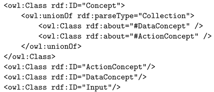
2) Ontology trees are of two kinds: DataConcept trees and ActionConcept trees. The relations among them are explicitly specified by their definitions. Examples of such definitions are the references to the input and the output of actions used in the domain algorithms.
3) New concepts are constructed by domain specific tree constructors which represent problem solving algorithms.
The methodology we use to build a domain ontology is similar to the “adaptive methodology” reported in [24] tailored to the goal of WBPSP. That is, the domain ontology reflects the problem solving process which evolves the ontology by the user learning process, and thus consists of two parts: a part that represents the user own ontology and a part that represents the domain expert ontology. Domain Expert Ontology (DEO) is built by hand, using a small taxonomy chosen from a textbook, is evolved by the process of domain expert education, and is updated during problem solving process. This is performed by a collaboration between domain expert and computer expert as shown in Figure 3.
The User Own Ontology (UOO) is built automatically by tools from the DEO, thus extending automatically the TBox and the ABox during algorithm execution by the DDVMs. That is, initially UOO coincides with the DEO. Then, during problem solving process UOO is automatically expanded with new concepts representing problems and solution algorithms developed by the particular user. Hence, at a given time, the domain ontology consists of the core DEO, that is available to all domain users, and a private part (UOO) which is specific to a given domain user. The DEO may be extended by the system to represent the domain evolution containing the new domain discoveries developed by the activity of the collection of domain users. This may be illustrated with the evolution of arithmetic ontology to a vector space.
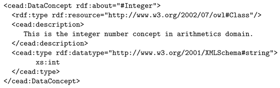
Consider an application domain modeled by a tree as shown in Figure 1. Data concepts represent data that can be used in a computational process such as input and output of such a process. The three attributes of a data concept are: type, value, literal. The type of a data concept is defined by the collection of operations
![]()
Figure 3. Domain ontology implementation and use.
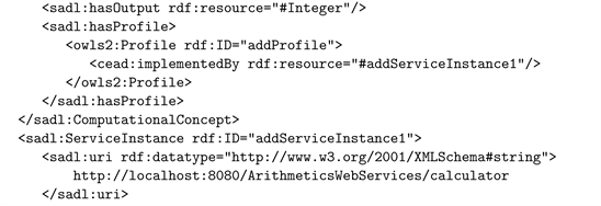
defined on that data; the value of the data concept is the abstraction it represents; and the literal is a string representing that data value during problem solving process. For example, Integer type is defined by the collection of operations identified by +, −, *, / where +, −, * are total operations and/is a partial operation; Integer values are decimal numbers and are formally defined as cardinals of sets; Integer literals could be sequences of decimal digits (potentially prefixed by + or −) representing integer numbers. Using appropriate definitions, one can extend the primitive operations +, −, *, / to the operations add, subtract, multiply, divide, which are defined on Number that subsumes both Integer and Rational.
The CEAD process associates both data concepts and action concepts of the domain modeled with WS-s which represent their semantics. As suggested in Figure 3, the WS-s are constructed by computer experts cooperating with domain experts. For example, the concepts in the arithmetic domain in Figure 2 are modeled by WS-s automatically generated from Java classes as we shall see further.
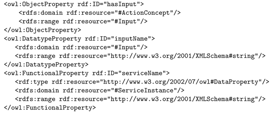
Computationally domain ontology is a data base, such as a file. Further we use the OWL file to represent a domain ontology where concepts are represented by their properties. As seen above, a data concept such as Integer, has three main attributes: type, value, and literal. These attributes are represented in OWL language by three properties: hasType, hasValue, and hasLiteral. Here we use the RDF triples to represent these properties which look like: Integer
URI (integerType), Integer
URI (integerValue), and Integer
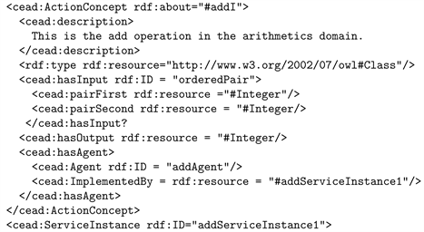
URI (integerLiteral). The action concepts like add, subtract, multiply, etc., are associated with WS-s which implements them via a Concept Agent. There could be several WS instances that implement the same concept so that if one instance is down other instances can take over. For example, the concept add may have the agent addAgent implemented by two WS instances: addInstance1, addInstance 2. The agent maintains the list of web services which it can execute as implementations of the action it performs. Therefore, the RDF triples that define an action concept a in the OWL file will look like: a
aAgent and aAgent
aInstance_1; …; aAgent
aInstance_n. For example, the add action of the Integer type is represented in OWL by the RDF triples: add
addAgent, and addAgent
add Instance 1, add Instance 2. The signature
of the add action is represented in the OWL file using the three RDF triples: add
IntegerPair, add
Integer, and add
addAgent.
5.2. Using Protegé for OWL File Development
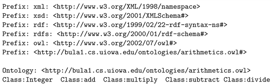
There are no software tools created to automatically generate an OWL file. Therefore we use Protegé to create and update an OWL file reprezenting a domain ontology. Hence, an OWL file representing a domain ontology is composed of a header and a body. The header tells us about the namespaces used in the ontology document and the ontology documents imported in the ontology document. Each namespace is specified by a Prefix construct and each ontology imported is specified by an Import construct. The body is basically composed of entity declarations (classes, properties, objects, individuals, axioms). Such declarations are in the form of RDF triples. We may use either XML syntax or OWL 2 Manchester Syntax [25] to express them. Though XML syntax is verbose, we believe that it is better understood by people and therefore we use XML syntax in the examples that follow. Since the goal of this paper is to describe a system that allows a computer user to perform problem solving using her computer as a brain assistant, we simplify the concept representation in OWL language and split the activity of OWL file creation in two steps. The first step is where the domain concepts are represented in the OWL file without being associated with web services implementing them, and the second step is where concepts in the OWL file are associated with their semantics. The first step is automatically performed by domain expert using Protégé tool [26], and second step is performed by the computer expert collaborating with domain expert. So far there are no tools assisting this activity. However, as we shall see in the next section, such tools can be easily developed.
Protege is an ontology editor tool which provides Graphical User Interface (GUI) so that the process of editing OWL files is easier. The user can create the OWL file by entering each concept as a class via the Protégé GUI. The subsumptions relation present in the domain model is called the sub-class relation in Protégé. The major benefit of using Protégé for the first step of the OWL file development is automatic creation of the OWL ontology file header. An example of an OWL file as created by Protégé is shown below. To gain space we collected all constructs Class:concept on one line though Protégé would place each of them on its own line.
5.3. Updating an OWL File with Web Services
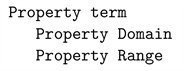
The file created by Protégé in the first step of the CEAD process represents a pure domain ontology where concepts are predefined (primitive) and are not associated with their implementations. We denote this file by domainPURE.owl. The second step of the CEAD process consists of creating the file domainCEAD.owl. This is initiated by including in the domainCEAD.owl the file domainPURE.owl. Then the entities in the file domainCEAD.owl are associated with computer artifacts implementing them, thus performing the second step of the CEAD process. This activity is standardized by the two kinds of knowledge we are handling: data concepts and action concepts. The patterns used to specify data concepts and action concepts consist of sequences of text lines where:
1) First line represents the domain term used to denote the concept;
2) Each line that follows represents a property (in the sense of OWL) of the concept specified on its previous lines. We use indentation conventions for the identification of the domain and range of the property, as follows:
Since we use WS-s as semantics of data concepts the primitive data are supplied by XML schema and are: xsd:int, xsd:double, xsd:boolean, xsd:string, xsd:time, etc., (see XML schema). All the other concepts are represented in terms of the predefined or already defined concepts.
The two kinds of patterns that represent the two kinds of concepts are:
1) Data concepts are specified by the pattern:

Example data concept is the Integer which when fit in the above pattern becomes:
2) Properties of the concepts are defined as XML elements whose tags are OWL properties ObjectProperty, DataProperty, FunctionProperty, whose ID attribute identifies the property name, such as hasInput, hasOutput, etc., and the XML element components define the domain, range, and the type of the property. Example property definitions are:
The description of namespaces, concepts, and properties in cead.owl follows a standard pattern. Therefore the examples given above are sufficient to understand the concept representation in arithmeticCEAD.owl that illustrates the domainCEAD.owl file. Here we illustrate WS generation for domain’s primitive concepts using the file ArithmeticsPure.owl. To simplify the matter we show only the web services associated with the data concept Integer and action concept add, and use XML syntax which we believe is more accessible to the reader. The rest of the entities of the ArithmeticsPure.owl ontology are treated similarly.


For convenience, the domain ontology file is associated with two dedicated namespaces: a names space called vocabulary, where all basic terms of the domain are collected, and a name space where the URI-s of the WS-s implementing the terms in teh vocabulary are collected. Since our example regards arithmetic domain and the WS-s implementing its terms are performed on the computer named bulai1 at the site cs.uiowa.edu using the sadl virtual machine, described in Section 6, the terms we used for these spaces are: http://bula1.cs.uiowa.edu/site/arithmeticCEAD.owl and http://bula1.cs.uiowa.edu/site/sadl.owl.
The computer artifacts used to represent concept semantics in the domainCEAD.owl file are in general developed by computer experts collaborating with domain experts. They can use any tools to implement them. The computer technology abounds of such tools [27] [28] [29] [30] and many other. These tools allow computer experts to develop WS by hand or to automatically generate them from conventional computer artifacts such as programs written in various programming languages as are Java, C, C++, etc. Among these tools Apache Axis is a light-weight, yet powerful tool for automatic WS generation from plain Java classes or C functions. We develop WS-s used to CEAD a domain of interest using two approaches:
1) WS-s associated with primitive concepts are automatically generated from Java programs using Apache Axis technology. The URL bula-site.documentation shows how do we use Axis2 in this project.
2) WS-s associated with user concepts defined during problem solving process are automatically developed by our own method as we shall see in Section 6.
6. Domain Dedicated Virtual Machine
The efficiency of the DAL algorithm execution by problem solver using the computer as a brain assistant is improved by associating each concept used in the
with the WS that implements it. This can be easily done by hand, by the problem solver, or by an appropriate automaton that operates on
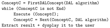
and OWL (D). The result can be seen as a “program” in the language of the brain assistant used by problem solver to execute the DAL algorithm. However, since the operations performed by this automaton (the brain assistant) are WS-s implementing the concepts of the problem domain, we call it the Domain Dedicated Virtual Machine (DDVM).
Formally, DDVM can be seen as a tuple DDVM =
where:
• ConceptC is a Concept Counter, that, for a given DAL algorithm
, points to the web service in the OWL (D), that implements the concept, to be performed next during the algorithm execution;
• Execute () is the process that execute the computations in the WS pointed to by ConceptC;
• Next () is a function which determines the next concept of the DAL algorithm
to be performed by Execute () during algorithm execution.
The DDVM performs similarly with the PEL (see Section 2) and therefore the algorithm execution by DDVM can be described by the following Domain Algorithm Execution Loop (DAEL):
On closer inspection one can easily see the similarity between DDVM and a Virtual Monitor [31]. The ConceptC is an abstraction of the program counter, the WS pointed to by the ConceptC is similar to the function executed by the OS simulating instructions of the machine implemented by the VM, and Next () is similar to the process that determines the next instruction of the program run by the VM. The difference is that the memory of the machine implemented by DDVM is the OWL (D), the processor of the DDVM is the collection of all processors available on the Internet (in the cloud) that implement WS-s used in the OWL (D), and the Next () is well defined by the relationship of the data and operations in the Polish form of the DAL algorithm expression. Therefore, the DDVM is a true domain dedicated virtual machine.
Once an application domain is CEAD-ed, the automation of DAL algorithm execution is based on two main software components:
1) A translator that maps the DAL algorithm into an expression tree whose nodes are labeled by domain concepts associated with the URL of the WS-s implementing them, and
2) An interpreter operating on the expression tree generated by the translator, executing WS-s encountered at the tree nodes.
The translator is implemented by the conventional compiler construction tools and the interpretor is implemented by a stack machine similar to Java Virtual Machine (JVM).
For a given DAL algorithm
the mapping of
into the expression tree
is automatically performed by the DAL parser, that transforms
into its parse tree,
. A bottom-up traversal of the
, that searches the OWL (D) for the domain concepts used in the
and associates them with the URL of the WS-s implementing them, maps the parse tree
into the expression tree
. The automation of the DAL algorithm execution using the WS-s available on the Internet requires the
to be transformed into an appropriate language that has WS-s as operations performed by DDVM. For this purpose we use the Software Architecture Description Language (SADL) [32] [33].
6.1. Software Architecture Description Language
Software Architecture Description Language (SADL), inspired by Armani [34], has been conceived as a language suitable to describe functional behavior of component-based software architectures, where components are standalone and composeable pieces of software. Hence, its goal is similar to the goal of the Intermediate Language (IL) used by Microsoft’s ASP.NET Framework. However, SADL evolved as a language suitable to describe functional behavior of component-based software architectures, where components are Web Services. Consequently the SADL software is designed to run on the network, therefore compiler construction technology provides a suitable mechanism to implement it.
As any language, SADL syntax has a three layer structure: vocabulary, simple constructs, and composed constructs. SADL vocabulary is a dynamic collection of terms used to denote problem domain concepts. Since SADL is meant as the target for any DAL implementation, it needs to be implemented as a domain dedicated namespace where each terms is associated with the collection of semantic properties that defines it in the respective domain. For example the term Integer in the SADL namespace of the High-School Arithmetic is specified by:
SADL vocabulary is the collection of DAL terms used by problem solvers in their DAL algorithms during problem solving process. Thus, from a computational viewpoint SADL terms denote computer process names. The code executed by these processes is associated with the term in the SADL namespaces and specifies completely the WS implementing that term. For example, the process executing the integer addition is associated with the term addI as follows:
The simple constructs of the SADL are simple XML elements:
where tag is a term in the SADL namespace and each attribute is a tuples of the form property = “value” where property is a property of the process (data are considered here as nulary operations) represented by the term tag. For example, the process that perform the addition of two integers is specified by:
where ari is the prefix of the arithmetic vocabulary namespace.
The composed constructs of the SADL language are XML constructs composed with the terms: foreach, if, ifthen, next, etc. Example, the SDAL expression of the formula:
is represented by the following XML code:
Note that SADL composition operators are provided as tags in the SADL namespace, as any other term of the problem domain.
SADL expressions are SADL representations of DAL algorithms.
6.2. SADL Interpreter
SADL interpreter inputs a SADL expression and interprets it on a stack, in a manner similar to the byte-code interpretation of a Java code. Since each SADL simple element composing a SADL expression represent a process executed on interned, the flow of control during a SADL expression evaluation requires synchronization of these processes. Thus, the SADL interpreter performs a distributed implementation of the DAL algorithm. The simplest synchronization mechanism used to control the flow of processes performing a DAL algorithm is provided by Unix wait and, signal primitives inserted in the SADL expression, after each SADL simple element. While this SADL implementation performs DAL algorithm distributed, on Internet, the algorithm execution is restricted to being sequential, where the computation unit is the WS. This mechanism can be extended to allow the processes performing a DAL algorithm to perform in parallel.
6.3. Evolving Domain Ontology
One of the key ideas of the DAL system is to provide a method that allows domain experts to create and extend their own CEAD-ed domain knowledge base. The DAL system solves this problem by allowing domain experts to create new action and data concepts.
6.3.1. Creating New Action Concepts
In order to create a new action concept, first of all, a domain expert expresses the new concept by an DAL expressions which is then saved in a file. Then she adds the concept to her UOO via an DAL Console program by executing “add2Onto
” command. This command translates the DAL expression into a SADL expression and sends it to her private space in the cloud, to which she subscribed. An Ontology Manager in the cloud automatically analyzes the submitted SADL expression and creates a new domain concept in the user’s UOO with a name specified in the DAL expression. The Ontology Manager also creates a web service broker which wraps around the SADL code so that the concept is available on the Internet as a standalone, composeable software component. All the information about this concept’s web service is automatically linked back to the user’s UOO so that newly created domain concept is CEAD-ed. From now on, the user can use that new concept as any other CEAD-ed domain concepts such as using it in a DAL Consoles or composing it with other CEAD-ed domain concepts in an DAL expression to express the user’s new computation.
The above scenario is demonstrated with the example in high school algebra that maps the algorithm solving quadratic equations into a new concept called Solver. We assume that the DAL expression of the algorithm that solves quadratic equations is written as follows and saved as the file solver.nld:
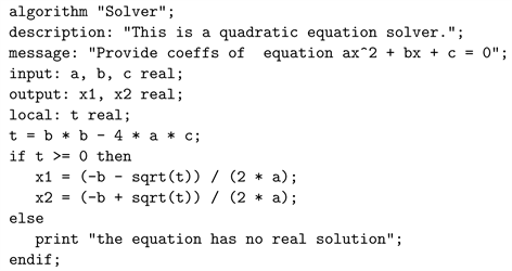
Then using the DAL Console the user executes the command
![]()
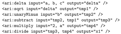
With the help of user’s profile, including user’s CEAD-ed ontologies and dictionaries, the DAL Console translates the above DAL expression into the following SADL expression:
![]()
This SADL expression is then sent to the Ontology Manager in the cloud. The Ontology Manager analyzes the SADL expression and creates a web service broker for this SADL expression at the URL address
![]()
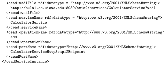
The Ontology Manager also creates a new entry in the user private ontology (
PURE.owl and
CEAD.owl) as follows:
![]()
Now the user can use the concept “Solver” as any other primitive concepts by executing the command use Solver. The user can also use this concept in another DAL expression as shown by the following example:
![]()
6.3.2. Creating New Data Concepts
DAL System is also provided with the mechanism that allows a user to add data concepts to her UOO. New data concepts must be defined as compositions of other known data concepts using such definition schemes as record, vector, set. Since all the known data concepts are represented as some XML data type, the DAL system represents the new data concept using an appropriate constructor record, vector, set that maps the user defined data concept into an XML data type. The method for a user to create a new data concepts are described in the following steps:
1) The user defines the new concept in an DAL expression as shown in the above pattern.
2) The user uses a DAL Console to submit the DAL expression to her private space in the cloud.
3) The Ontology Manager in the cloud receives the DAL expression and analyzes it.
4) When the Ontology Manager finds a data concept definition:
a) Creates the corresponding domain data concept and add to the user’s UOO.
b) Creates a new XML Data type which represents the data concept following the above pattern.
c) Automatically link the newly created data concept with the corresponding XML Data type.
5) The CEAD-ing process for creating new data concept finished.
We illustrate the mechanism of extending domain ontology with new data concepts with the example where a user defines the data concept Complex that represents complex numbers in the high school arithmetic domain. Since a complex number is a record of two real numbers the user defines the concept Complex using the following DAL expression:
![]()
The XML schema used to transform this DAL expression into a SADL expression is:
![]()
In the case of the Complex concept, we have the following concrete XML data type definition:
![]()
7. DAL System
DAL System provides a user-dedicated implementation of a computer. That is, a computer user who installs this system on her computer can further use the computer as a brain-assistant dedicated to her problem domain. Since the computer use lacks the efficiency when used in this manner we chose to describe here the implementation of the system in the cloud. This manner of DAL System implementation dedicates the system to a problem domain, thus allowing the computer to be shared among many users, who in effect share the problem domain in a manner in which the students of a class share the class instructor’s knowledge.
7.1. Cloud Implementation of DAL System
Cloud-implementation of the DAL System is described in Figure 4. The assumption is that CC that accommodates the DAL System would have an administrator that manage the system allowing various users to register for DAL System use on a given problem domain. For that the CC is provided with a data base where all the SEAD-ed domain ontologies are maintained. The user subscription for a domain D is performed by an installation procedure that activates DAL System with the domain ontology required.
![]()
Figure 4. Architecture of an DAL system.
![]()
Figure 5. Interacting with an DAL system.
Further, as shown in Figure 4, the user customizes the system to her personal use, evolving the problem domain she subscribed for with the concepts she learned and/or created during her own problem solving process. When the user decides to leave the system and cancel her subscription, the DAL System’s manager my buy the knowledge developed by the user and update the domain, thus ensuring domain evolution with the concepts developed by the respective user. This ensures a domain evolution with the knowledge developed by problem solving process of all domain experts.
7.2. User Interaction with DAL System
A user doesn’t need a computer in order to interact with the DAL System. An iPad (or any other display) which provides a two-way communication using a command language can be used in this purpose. We envision here a Unix shell interaction as described in Figure 5.
The DAL System is not appropriate for iconic-language implementation because it manipulates concepts that can be created by the user. Since the system is natural language based, and natural language is infinite through the infinite sequences of human generations speaking it, Window-implementation, though possible, would not be appropriate.