Design and Implementation of QPSK Optimal Band Transmission System Based on Software Programming ()
1. Introduction
The rapid development of social science and technology is inseparable from the most basic communication. Communication system is still the basic technology in different fields. Because digital communication can flexibly transmit and process various kinds of data, digital communication system technology has become the focus of today’s research work. The digital communication system is inseparable from modulation technology, in which QPSK (quadrature phase shift keying) modulation [1], can make good use of the very scarce spectrum resources in communication and resist the interference of inevitable noise in the communication process. At the same time, QPSK modulation can well balance the relationship between received signal-to-noise ratio and frequency band utilization. This modulation technology has been applied in satellite communication. The most common problem in the transmission of digital signals is inter symbol crosstalk (ISI), which leads to inaccurate information reception and higher bit error rate. It is our goal to design a communication system to eliminate inter symbol crosstalk and achieve the best reception. At present, there are many software realization methods of frequency band transmission system based on QPSK modulation and demodulation technology, including Matlab language, C language, VHDL language, Systemview and so on [2] [3]. In the software design, the technology of QPSK modulation and demodulation is very simple, but the design and implementation of digital matched filter in the QPSK optimal frequency band transmission system based on the best reception theory is a problem that needs to be solved. The method adopted in this paper is as follows: The signal into the digital matched filter is sampled and processed. After sampling and processing, the signal meets the requirements of the physically realizable digital matched filter, so as to realize the design of the physically realizable digital matched filter.
The R & D of communication technology has spread to many fields and industries, and the demand for communication talents has increased significantly. Research institutes, enterprises and start-ups need design talents who can carry out new system design, innovative algorithm design and develop complete communication systems. Now the communication system design is basically a software programming work with communication principle and signal processing knowledge. In order to meet this requirement, this paper completes a complete QPSK optimal band transmission system software design and programming experiment. Through the software design and programming experiment of QPSK optimal band transmission system, people can understand how communication theory and technology can be realized through software programming, understand the software attributes of communication system design, and learn the complete communication system software design and implementation process and method [4] [5]. On the other hand, the designed QPSK optimal band transmission system includes important basic communication theoretical knowledge such as M-ary modulation technology, inter symbol crosstalk elimination technology and optimal reception technology, which is of typical significance for understanding communication theory and practical implementation technology. In addition, after the software programming design is completed, you can directly download the software radio and switch to the real-world experiment to realize the transformation from theoretical design to real-world application, which lays a foundation for follow-up research and product development.
2. QPSK Optimal Band Transmission System
2.1. System Composition
QPSK optimal band transmission system is shown in Figure 1, which is composed of transmitting part, channel and receiving part. The transmitting part includes digital signal input, serial/parallel conversion circuit, level conversion processing, sampling, root raised cosine transmission filter and QPSK modulation
![]()
Figure 1. QPSK optimal band transmission system.
circuit. Channel: communication channel with Gaussian white noise. The receiving part includes: demodulation circuit of QPSK signal, root raised cosine receiving matched filter, level conversion processing, sampling, decision, parallel/serial conversion circuit and digital signal output.
2.2. Implementation Principle of System
In the circuit structure of the designed QPSK optimal frequency band system, QPSK modulation is realized by orthogonal phase modulation method, that is, the input serial unipolar symbol sequence signal is transformed into parallel double bit bipolar code stream through serial parallel transformation, which enters the in-phase branch (called I channel) and quadrature branch (called Q channel) respectively, and the waveform gT(t) is formed through root raised cosine transmission filter, which is multiplied with quadrature carrier respectively, Two 2PSK signals are obtained, and the QPSK signal is synthesized. Its principle is shown in Formula (1). QPSK demodulation is realized by 2PSK coherent demodulation of two coherent orthogonal carriers (I channel and Q channel) [6] [7] [8]. The root raised cosine transmitting filter at the transmitting end and the root raised cosine receiving filter at the receiving end eliminate the inter symbol crosstalk and have the best anti noise performance of the QPSK transmission system, that is, realize the best transmission of QPSK, and the transmission system can be physically realized.
(1)
In Equation (1), ei(t) represents QPSK symbol signal, gT(t) represents the waveform of baseband signal, i = 1, 2, 3, 4 0 ≤ t ≤ T s.
3. Software Design and Implementation of QPSK Optimal Band Transmission System
According to the structure of QPSK optimal band transmission system in Figure 1 and based on MATLAB software platform [9] [10] [11] [12], each module of the system in Figure 1 is programmed and realized, and its functions are completed.
3.1. Software Design of Transmitting Module
The transmission of the signal of the transmitting part is: the unipolar non return to zero input signal sequence is transformed into a bipolar non return to zero signal sequence through serial/parallel transformation, and then processed into a bipolar non return to zero signal sequence through level transformation. After being output through sampling and root rising cosine filtering, the output QPSK modulation signal is generated by the QPSK modulator and sent to the channel. Parameter setting: carrier frequency fc = 5 MHz, bit rate R = 5 Mbuad, transmit data 50 kbit.
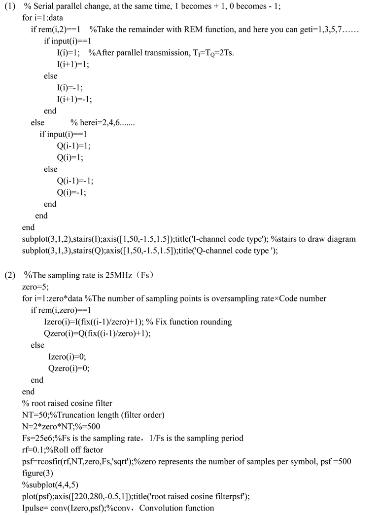
1) Design of serial/parallel conversion and level conversion module
The design realizes the conversion of serial data into parallel data, and the completion signal “0” code level is assigned as +1, and the “1” code signal level is assigned as −1. Note that the duration of parallel symbols is twice that of serial codes. See Appendix A (1) for some key codes of software design.
2) Sampling, root raised cosine transmission, filter module design
It should be noted here that the signal should be sampled and processed to meet the index requirements of the actual realizable filter. Parameter design: adoption rate FS = 25 MHz, 5 sampling points per symbol, roll off factor α = 0.1, filter order NT = 50. See Appendix A (2) for some key codes of software design.
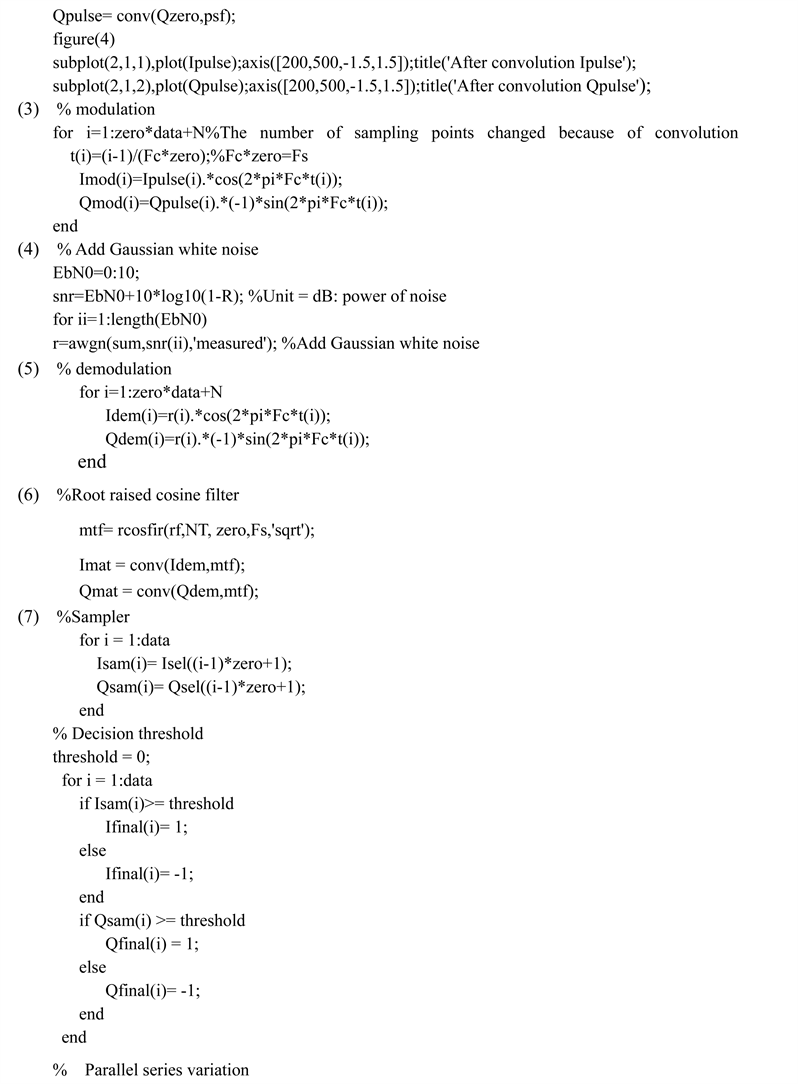
3) QPSK modulation module design
See Appendix A (3) for some key codes of software design.
3.2. Channel Module Software Design
The signal plus Gaussian white noise forms the transmission signal in the channel. See Appendix A (4) for some key codes of software design.
3.3. Receiving Module Software Design
The transmission of the received part of the signal is: after the QPSK signal is demodulated, it is received and filtered by the root rising cosine, which is changed from the sampling and decision circuit to the high-level and low-level signal, and then changed into the unipolar non return to zero signal sequence through level conversion, and the digital signal is output after parallel/serial conversion. Parameter setting: coherent carrier frequency Fc = 5 MHz, root raised cosine filter sampling rate Fs = 25 MHz, sampling decision interval 0.2 μs, roll down factor α = 0.1.
1) QPSK design of signal demodulation module
See Appendix A (5) for some key codes of software design.
2) Design of root raised cosine receiving filter module
The root raised cosine receiving filter can eliminate ISI, See appendix A (6) for some key codes of software design.
3) Design of sampling, decision and parallel/serial conversion module
See Appendix A (7) for some key codes of software design.
3.4. Software Design of System Signal Spectrum and Bit Error Rate Test Module
In order to analyze the system signal spectrum and detect the bit error rate of the system transmission, the signal spectrum diagram display module and bit error rate calculation module are designed. The signal spectrum is simulated with this module, and the bit error rate index of the designed system is calculated.
4. Analysis of Operation Simulation Results
After the QPSK optimal frequency band transmission system designed by software programming is completed, the debugging operation is correct, and the simulation experimental results of signals in each transmission link of the system are obtained: the waveforms of input signals, I-channel and Q-channel signals are shown in Figures 2(a)-(c). The root raised cosine transmission filter and the I-channel and Q-channel waveforms after filtering are shown in Figures 3(a)-(c). It can be seen from Figure 3 that the root raised cosine waveform with roll off characteristics has no inter symbol crosstalk and can be physically realized at the symbol decision time. The I-channel modulation, Q-channel modulation and QPSK signal waveforms of QPSK modulator are shown in Figures 4(a)-(c). It can be seen from Figure 4 that the modulation phases are π/4, 3π/4, 5π/4, and 7π/4, and the phase corresponds to the double bit gray code. The transmission waveform of QPSK signal Gaussian noise channel is shown in Figure 5. It can be seen from Figure 5 that QPSK signal is interfered through channel transmission. The demodulation waveforms of QPSK signal I and Q channels are shown in Figure 6(a) and Figure 6(b). It can be seen from Figure 6 that QPSK signal has been demodulated. The output signal waveform of channel I through the root raised cosine receiving filter and channel Q through the root
![]()
Figure 2. Input, I-channel, Q-channel signals. (a) Input; (b) Channel I; (c) Channel Q.
![]()
Figure 3. Filter, filtered I-channel and Q-channel waveforms. (a) Root raised cosine transmission filter; (b) I-channel convolution; (c) Q-channel convolution.
![]()
Figure 4. I, Q, QPSK modulation signal waveform. (a) I-channel modulation; (b) Q-channel modulation; (c) QPSK signal.
raised cosine receiving filter is shown in Figure 7(a) and Figure 7(b). Figure 7 shows that the signal waveform with roll off characteristics is output after the root raised cosine receiving filter. The inter symbol interference at the judgment time of this waveform is very small and can be physically realized. The two signal waveforms obtained after I-channel selective sampling and Q-channel selective sampling are shown in Figure 8(a) and Figure 8(b). I-channel Q-channel. The signal waveform after decision and serial parallel conversion is shown in Figures 9(a)-(c). It can be seen from Figure 9 that the output digital sequence eliminates inter symbol crosstalk, and the original transmitted signal sequence is compared with the output signal sequence Figure 9(c) without error. The QPSK
![]()
Figure 6. Demodulation waveforms of I, Q. (a) I-channel demodulation; (b) Q-channel demodulation.
![]()
Figure 7. I-channel sampling. (a) I-channel post modulation filtering; (b) Q-channel post modulation filtering.
signal spectrum is shown in Figure 10. It can be seen from Figure 10 that the QPSK signal is a bandpass signal. Set the transmission of 50,000 symbols (no error can be seen when there is little transmission data), and the bit error rate results of the tested QPSK best band transmission system are shown in Figure 11. It can be seen from Figure 11 that when Eb/N0 reaches 10 dB. The bit error rate of the whole system is only 0.00018, That is, bit error rate 1.8 × 10⁻⁴, which meets the actual requirements. In order to verify the performance of QPSK
![]()
Figure 8. Signal waveform after I-channel and Q-channel sampling. (a) I-channel sampling; (b) Q-channel sampling.
![]()
Figure 9. I-channel, Q-channel decision, system output signal waveform. (a) Route I judgment; (b) Route Q judgment; (c) QPSK system output.
optimal transmission, a QPSK non optimal transmission mode without root raised cosine filtering is designed. The simulation curve of bit error rate of both is shown in Figure 12. It can be seen from Figure 12, when Eb/N0 = 10 dB, the bit error rate of QPSK optimal band transmission system is 5 × 10⁻⁵, while that of QPSK non-optimal band transmission system is 2 × 10⁻³. As a result, that the bit error performance of QPSK optimal band transmission system is better than that of non optimal transmission.
The analysis of simulation results shows that the QPSK optimal band transmission system and all parts of the system have completed their functions and meet the performance index requirements. Therefore, the system realized by software programming is feasible through operation experiments, and the design of the whole system is reasonable and meets the design requirements.
5. Conclusion
Through the software design and programming experiment of QPSK optimal frequency band transmission system, the implementation software of QPSK optimal frequency band transmission system is completely written. The specific process and method of communication system programming design are introduced in detail. Through the experiment of software design communication system, we should especially realize the gap between actual communication and communication theory, how to transform communication theory into actual communication system, and pay attention to solving this problem in software design communication system. After running the programmed QPSK optimal frequency band transmission system, the simulation results verify that the QPSK communication system experiment designed by software programming completes its function and meets the requirements of system performance index. Through this design example, people can fully understand how communication theory and technology can be realized through software programming, understand the software attributes of communication system design, and learn the software design and implementation process and method of complete communication system. At the same time, the results of this software programming communication system method are applied to our experimental teaching of communication system theory. Students will complete the communication system experiment through their own programming design, will be more able to deeply understand and master the theoretical knowledge and technology of communication principle, and will be more interested and motivated to learn communication system theory. More importantly, after the completion of the software programming communication system, you can directly download the software radio and switch to the real-world communication experiment, so as to realize the transformation from theoretical design to real-world application, and realize the goal of cultivating talents for communication system software design.
Appendix A