Current Distortion Evaluation in Traction 4Q Constant Switching Frequency Converters ()
1. Introduction
The four quadrant converter (4Q) is the actual best choice to supply the DC voltage link from AC power contact line. A typology of distributed power high speed electric trains having as input stages more 4Q converters [1] has been considered.
The presence of more converters is necessary to guarantee a good redundancy in case of failure and gives the opportunity, using dedicated control logics, to interlace them in order to reduce the harmonic content of the absorbed current. The high power requested by the train for its acceleration in starting phase and for the auxiliary services needs high power converters that do not allow high switching frequencies. Consequently the absorbed current presents a high ripple value characterized by high harmonic current components that cannot be tolerated by the system. Indeed the track circuit used for signaling and communication for the traffic management and safety employs signal currents overlapped with the power ones. These currents can have low frequencies (50 Hz and 178 Hz) in the traditional signaling system, or they are in the audio frequencies range for the new European ERTMS/ ETCS one. Therefore, the harmonics produced by the 4Q converter can disturb the communications of the track circuit, degrading the safety of the trains circulation. On the other hand the 4Q converter has the main benefit to give a nearly sinusoidal line current in both directions of energy flow and the mitigation of reactive power drawn from the line. In fact the 4Q converter is based on the use of forced commutation switches (GTO, IGBT) and presents a sinusoidal current absorption in phase with the contact line voltage. Moreover, this converter is intrinsically bidirectional and then it can be used both for traction and regenerative braking phases.
The aim of this paper is an analysis of the current absorbed by the high speed trains through a suitable model of more 4Q converters. Thanks to a control logic applied in this work, it is possible to interlace two or more converters in order to evaluate the harmonic contribution of both single converter and the interlaced configuration. The simulation results obtained with an electromagnetic analysis will be presented.
2. Mathematical Model of the 4Q Converter
The principle scheme reported in Figure 1 shows how the four-quadrant converter is structurally equal to a single phase voltage source inverter and employs the same switches used for the motor drives. This is an advantage because the various branches can have a modular construction [2]. The system includes:
◆ he transformer secondary side;
◆ four switches (GTO or IGBT), T1 ÷ T4;
◆ four freewheeling diodes D1 ÷ D4;
◆ a DC link with capacitive middle circuit C between the terminals AK and working at the imposed voltage Vd=cost;
◆ a second harmonic filter L2–C2 placed downstream the main bridge, tuned to a frequency f2=2·f1 double to the line one.
The system has two main purposes. The first one is the absorption from the contact line, at a voltage e1 and frequency f1, of a current having the fundamental harmonic i1 in phase with e1 and with low harmonic content, in order to respect the following conditions:
 (1)
(1)
The second purpose is the absorption from the line of a power with a mean value P1, pulsing at the frequency 2·f1 and the supply of the three-phase motor drive inverters connected to the dc link with a continuous power Pd.
In order to study the behaviour of this converter, the modelling process starts by a mathematical representation of the discrete operation modes of the converter. The discrete model describes each working mode through separate equations. Figure 2 shows a simplified representtation of the two-level converter from which the discrete model is derived.

Figure 1. Principle scheme of a four-quadrant converter. e1=line voltage at a frequency f1; i1=line current

Figure 2. Equivalent circuit of a four-quadrant converter
In the equivalent circuit of Figure 2, the transformer secondary side is represented by:
◆ an ideal voltage generator (e2=e1/h, where h is the transformer ratio);
◆ an inductance L, equivalent to the leakage transformer one;
◆ a resistances Rs mainly due to the switches;
◆ load resistances R0;
◆ DC link capacitance C.
Considering the state variables is and vc, the converter state equations are the following:
 (2)
(2)
where ω is the angular frequency. Rewriting these equations in matricial format, it comes out:
 (3)
(3)
or  where x is the state vector and
  is its time derivative.
Taking into account that the converter is a two level type, there is another possible operation mode, described by the following matrix A:
 (4)
(4)
Looking at the matrix A, it is possible to note that in these two operation modes the first element of the first row and the second one of the second row are the same. Therefore, the state equation can be rewritten to:
 (5)
(5)
where x depends from the operation mode and can assumes the value 1 or -1.
In this analysis, the switches resistance Rs has been neglected.
The transformer leakage reactance depends by the contact line frequency:
 (6)
(6)
and it causes a lagging phase shift of an angle ψ between the converter voltage  and the supply one
 . Therefore the first harmonic component of voltages and current become:
 (7)
(7)
where the rms value of the AC voltage v2 is related to the DC one Vd through a proportional coefficient:
 (8)
(8)
The DC link voltage of the single-phase converter has a significant ripple component at twice the supply frequency. In fact, as it is possible to note in Figure 1 and reported in [3], the current i given by the 4Q converter to the middle circuit is composed by two components:

where:
 (9)
(9)
is the direct component of the i(t) responsible of the power absorption, and
 (10)
(10)
is an harmonic at the frequency f2=2·f1, with the following rms value:
 (11)
(11)
The is(t) is absorbed by the dedicated filter L2–C2 tuned at frequency f2 so that into the dc section that feeds the motor inverter flows the only continuous component Id.
Referring to the control, a smart modulation [4] has been applied, where the input current follows a suitable sinusoidal reference in order to have a sinusoidal absorption, as explained in the following paragraph.
3. Current Modulation
In order to have a sinusoidal absorption the input current follows a suitable sinusoidal reference.
The AC reference current is obtained by multiplying the AC line voltage with a suitable equivalent conductance, in accordance with
 (12)
(12)
where is the phasor of the AC phase current and
  is the fundamental component of the AC contact line voltage.
The AC voltage contains the fundamental component and the component v" corresponding to the perturbations present in the AC line (i.e. harmonics), the Park vector of the AC voltage being
 (13)
(13)
Thus, the instantaneous real power, expressed as Park vector, is given by
 (14)
(14)
where  is the complex conjugated value of
 .
.
Considering null power losses associated with the single phase converter, the AC - DC power balance is given by
 (15)
(15)
and the DC current, neglecting the ripple, can be expressed with
 (16)
(16)
Considering the currents flowing through the DC bus, a non-linear relation between the DC voltage vdc, the control variable G and the load current iload is obtained
 (17)
(17)
Since V1 can be considered constant, the (17) can be linearized as follows:
 (18)
(18)
d represents a perturbation, due to the AC line disturbances and the DC ripple.
For the DC voltage control, a proportional–integral (PI) controller has been chosen. Its transfer function is
 (19)
(19)
where F(s) is the transfer function of the low pass filter required for reducing the DC bus ripple.
The Equations (18) and (19) constitute the closed loop of the DC voltage control that allows computing the values of the PI parameters. In a first approximation the transfer function F(s) can be neglected, obtaining
 (20)
(20)
The denominator, considering a damping ratio of 0.707, constrains the PI controller parameters to respect the following relations:
 (21)
(21)
4. Model of the System
In order to validate the theoretical analysis above described, a suitable model of the system has been implemented in the EMTP-ATP dynamic simulation tool. The data employed for the modelization refer to a real High Speed Train operating in Italy in 25kV–50Hz lines. This

Figure 3. Traction circuit schematic diagram of the Italian high speed train

Figure 4. Block diagram of the implemented model of the system
vehicle is constituted by two locomotives with two motor drives each. Every motor drive is supplied by double 4Q converters input stage through the main transformer as depicted in Figure 3.
Each 4Q converter is sized for a rated power equal to 900kW and a maximum peak power equal to 1500kW. These are relevant power values for a switching converter that has to be small and light enough to be installed onboard.
The 4Q converters are constituted by a power part and a control one. The power circuit has been modeled with the circuital elements already available in EMTP-ATP. The MODELS language has been used for implementing the proposed converter control.
The final schematic model is reported in Figure 4, where it is shown only one of the two input stage 4Q converters.
In the block diagram represented in Figure 4 three control loops can be identified. The first one is the DC link voltage control loop constituted by the voltage measurement, the low-pass filter explained in the previous paragraph, the comparison with the reference value V0ref and the PI controller. Its output is the value of the equivalent conductance G that keeps the DC link voltage constant varying the power requested or injected by the traction motors and auxiliary services. The second loop is the reference current generator. It considers the input voltage measurement followed by a filter dedicated to the high frequency disturbances. The obtained value multiplied with the equivalent conductance G gives the reference current that the converter, through the switching modulation, has to generate in order to balance the input and output powers. The third loop is related to the DC component compensation in the AC input current. In fact its output value is a constant current that, algebraically added to the reference one, allows to cancel the DC component avoiding the saturation of the input transformer.
5. The Interlacing of the Converters
The use of modulation techniques at constant frequency [5] lets an opportunely shifting of the switching time for the different 4Q converters onboard the train.
The final goal is to interlace more converters in order to diminish the harmonic content in the total absorbed current. The interlacing operation gives a shifting through the current waves coming out from the converters that have to be the one that minimize the harmonic content.
In order to preliminary study the benefit of the interlacing practice, two boost converters are considered. As reported in Figure 5, their current waves are shifted of a generic angle φ.
The two waves have the same duty cycle δ and they are only shifted of the angle φ. Therefore the Fourier series f and f' of the two converters are the following:


Applying the known trigonometric formula, the f' can be rewritten as:

Figure 5. Waves shifting of the two interlaced boost converters currents
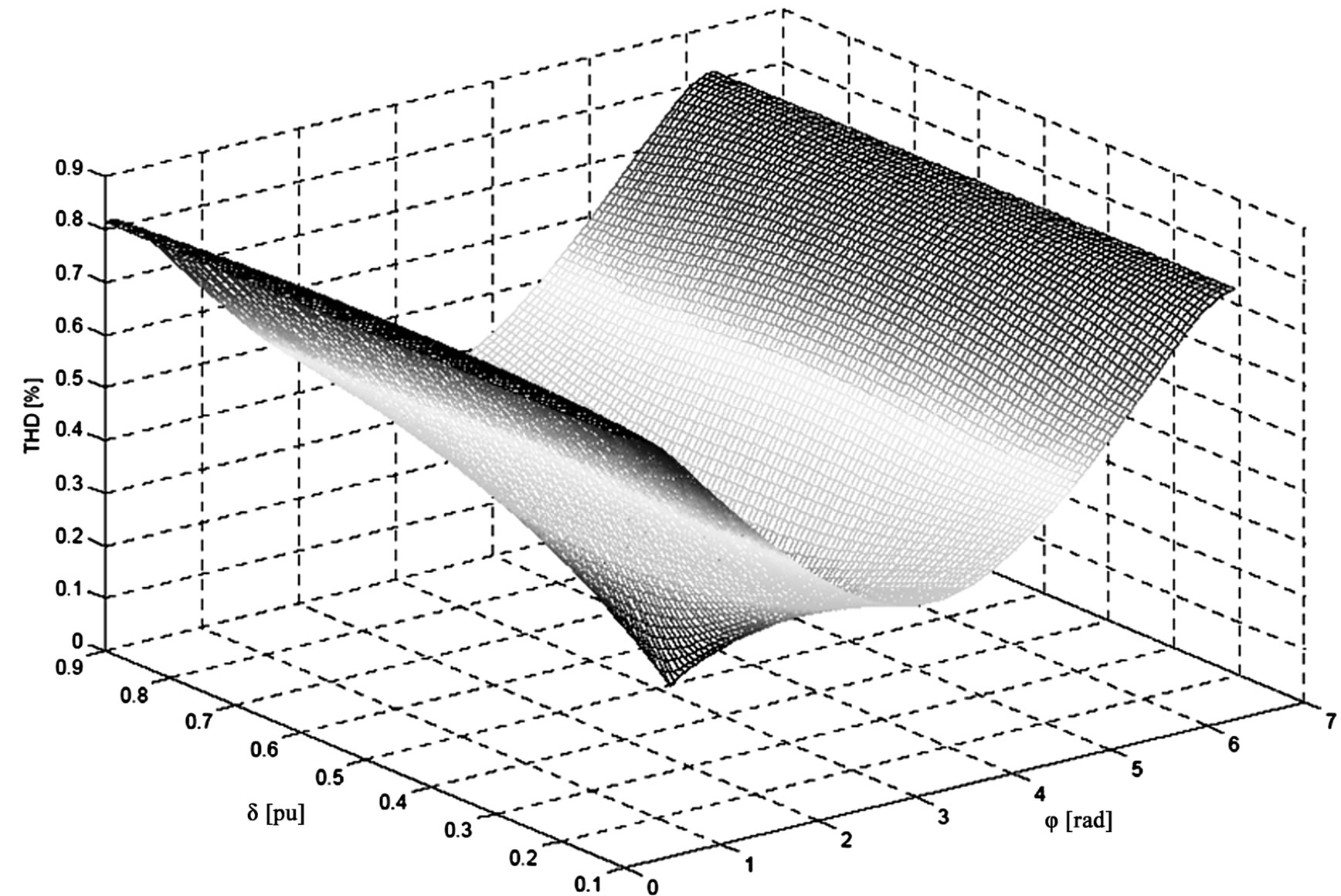
Figure 6. Behavior of the THD, varying the duty cycle δ and the shifting φ between the currents absorbed by the two boost converters
Applying the known trigonometric formula, the f' can be rewritten as:
where:

Considering that the current absorbed by the train is the sum of the currents absorbed by the two converters, the resulting function to consider for the THD calculus is given by the sum of the two functions, that means:

with  and
and .
.
In this case the absolute THD is defined as following:
 (22)
(22)
with .
.
As it is possible to note, in the THD calculation the first harmonic has been also considered , referred to the switching frequency, because all the ripple is an undesirable component. The THD so calculated is function of the shifting angle φ between the two waves and of the duty cycle δ, here supposed the same for the two converters.
In order to underline the THD dependence from the parameters δ and φ, a simulation in Matlab environment has been carried out. The (22) has been considered, varying the duty cycle between 0.1 and 0.9 and the shifting between 0 and 2π and supposing the current ripple amplitude equal to the 1% of the continuous component. The result is reported in Figure 6.
From Figure 6 it is possible to make some considerations. First of all, as expected, the THD is null for δ=0.5 and φ=π, because it is the only case in which the two triangle waves are symmetric and in opposite phase, therefore all harmonics are cancelled.
From the optimal point, the THD initially grow fast, both varying δ and φ, underlining the fact that also small dissymmetry in the two converters switching diminish the advantages given by the interlacing. The optimal shifting φ is always equal to π and in this case the THD is always minor than the case of not interlaced converters (φ=0).
Finally, the THD is directly proportional to the ripple amplitude respect to the DC component, and for this the

Figure 7. Shifting of the four switching frequencies

Figure 8. Line voltage waveform measured on the secondary side of an auxiliary transformer
effective values coming out from the practical cases are higher than the ones reported in Figure 6, considering the relevant current undulation due to the low switching frequencies.
Taking into account the different typologies of interoperable locomotives and electro trains normally running on the railway lines, it is possible to note that after each input transformer there are 2 or 4 4Q converters. Each converter is supplied by a dedicated winding of the main transformer.
It comes out that, in order to have a good interlacing, the shift of each converter switching frequency has to be respectively equal to ½ or ¼ of the switching period.
In this way the ripple of the current absorbed by the transformer due to all the 4Q converters has the main frequency equal to two or four times the switching one with the advantages of a minor amplitude and easier filtration.
In Figure 7 is possible to note the shifting of the four switching frequencies.
Analyzing the smart modulation here applied, it is possible to note as the commutation instants are calculated starting from points on the reference current that have the same time distance. The interlacing can be easily obtained intercalating these time instants referred to the different converters.
6. 4Q Converters Model for Harmonic Analysis and Simulation Results
In order to evaluate the harmonic contribution of the 4Q converters in single operation and in interlaced configuration, some numerical simulations are carried out, using ATP/EMTP program.
These converters are often supplied by a distorted input voltage, due to the low short circuit level of the railway lines and a greater harmonic content allowed by the dedicated standards. A typical waveform measured on the secondary side of the transformer for auxiliary services ins reported in Figure 8.
The most significant components are reported in Table 1.
This distortion is mainly due to the resonance phenomena along the line, also enhanced by the harmonic current injected by the trains. In order to have a correct operation of the 4Q converters it is necessary to have a cleaner input voltage obtained installing LC filters in the input stage. Moreover, the greater components (>50th) are carefully
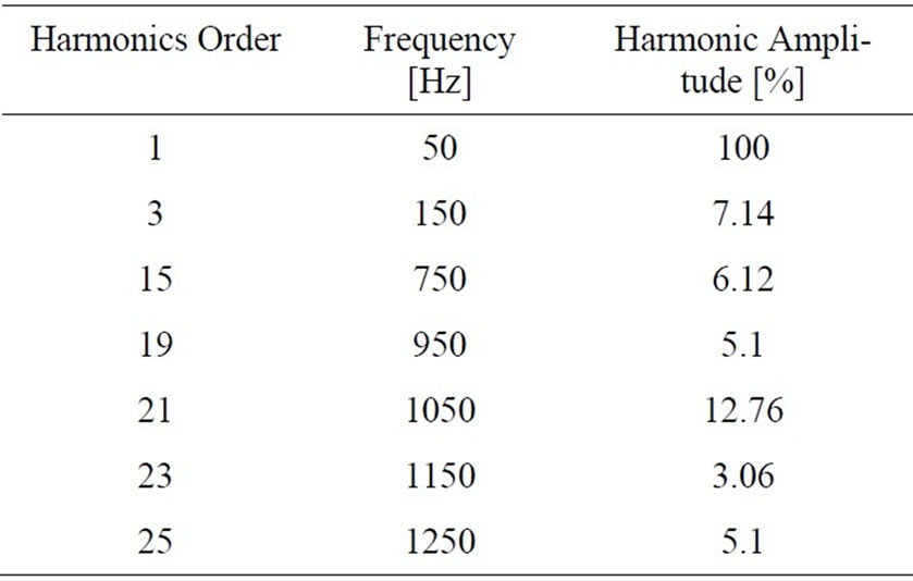
Table 1. Harmonic content of the line voltage recorded during a measurements survey
filtered to avoid interference with signaling system.
In this analysis, each 4Q converter has been studied considering the following characteristics:
◆ rated voltage of the contact line: 25 kV, 50 Hz;
◆ transformation ratio of the onboard transformer: 25/0.7 kV;
◆ DC link voltage: 1800 V;
◆ rated power: 900 kW;
◆ switching frequency: 500 Hz.
The power components of the converter have been modeled with ideal switches, while the DC load with current generator. A negative value represents the current absorbed during the traction phase, while a positive one represents the regenerative braking.
In the controller are implemented two control loops.
The first one gives the value of conductance G that multiplied by the input voltage determines the input current reference. The value of the equivalent conductance G is obtained through PI controller comparing the measure of the DC link voltage with its reference in order to keep the DC voltage constant at its nominal value of 1800 V. The function of this controller is to guarantee the equivalence between the input power and the one absorbed by the load. In order to assure a uniform power absorption among the various converters, there is only one regulator for all the converters.
The second loop is necessary to cancel the DC component in the AC current that can be generated by the low switching frequency of the switches. This DC components can be dangerous for the onboard transformer because can saturate the magnetic core. Indeed this transformer is not oversized due to the need to reduce its weight and volume. Therefore it is really sensible to the direct current component. Because the four 4Q converters are supplied by four independent transformer windings, it is necessary to adopt one of these regulators for each converter. In Figure 9 the current absorbed by one 4Q converter and its Fourier analysis are reported. It is possible to note a high ten order components corresponding to the switching frequency, but also an appreciable third harmonic. This last one is due to the difficulty to follow up the sinusoidal reference having a so low switching frequency.
The interlacing of the four converters has really reduced the harmonic content, as it is well represented in Figure 10, where the current absorbed at pantograph and its Fourier analysis are reported. In particular there are no more harmonics at the switching frequency, but there is still the third harmonic, due, as told before, to the low switching frequencies.
What told above is confirmed by Figure 11, where it is possible to note that there is a difficulty of the converter to switch at the end of each half period.


Figure 9. Current absorbed by one 4Q converter and its Fourier analysis
In order to better evaluate the contribution of the four converters interlacing in improving the current waveform, the out of service of one converter has been considered. This condition can occur during the train operation.
The current absorbed at pantograph in this second case with only three 4Q converters working and its Fourier analysis are reported in Figure 12.
It is possible to note the worst harmonic content respect to the previous case and, most of all, the contribution of the switching frequency comes out again. In fact it is evident the presence of the ten order component. Regarding the third harmonic, the situation is not changed, always due to the low switching frequency.
In Figure 13 is reported the shifting of the three switching frequencies and also in this case it is evident the difficulty of the converter to switch at the end of each half period.
7. Conclusions
The paper deals with a power quality analysis regarding the input stage of the modern interoperable high speed trains constituted by more four quadrant (4Q) converters. In fact, the use of the 4Q converter allows to overcome the limits imposed by traditional rectifier.
However, the high power needed for the train acceleration, in the order of 6000 kW per locomotive, does not allow to have high switching frequencies. In fact, in the


Figure 10. Current at pantograph in case of four 4Q converters working and its Fourier analysis

Figure 11. Currents absorbed by all the four 4Q converter interlaced
recent realization they reach the maximum value of 500 Hz. Consequently the absorbed current presents a high ripple value not always tolerable by the system.
The presence of more converters gives the opportunity, using dedicated control logics, to interlace them in order to reduce the harmonic content of the absorbed current at the pantograph.
Computer simulations have been carried out using a suitable model of more 4Q converters, for determining the contribution of the interlacing in improving the current waveform.
First, the case of four interlaced 4Q converters has


Figure 12. Current at pantograph in case of three 4Q converters working and its Fourier analysis

Figure 13. Currents absorbed by three 4Q converter interlaced
been analyzed. In particular the analysis shows that the nterlaced operation allows the reducing of the absorbed current ripple, since the equivalent switching frequency is four times the single converter one. However the low harmonic components, such as the third one, cannot be canceled by this solution, therefore they have to be filtered by traditional LC passive filters.
The second case analyzed regards a condition that can occur during the train operation such as the out of service of one converter. In this situation the performances of the train are guarantee by the other three converters, even if it is not possible to completely cancel the harmonic component at the switching frequency.