Design and Implementation for Ladder Diagram in Hydropower Simulation System Based on All Paths Searching Algorithm ()
1. Introduction
Recently, great changes have arisen in the electrical virtual instruments, e.g. the hydropower simulation system [1–4]. It is a comprehensive system including hydraulic, water conservancy, mechanics and autocontrol. LD control system plays an important role in the system, so an user friendly design interface component-based should be developed for users, and meanwhile, unlikely in the PLC, the control function of LD must be implemented without compiler or interpretation.
Reference [5] proposed a control modeling approach using PNs, an automated CNC lathe door interlocking control program is used as an example, for which model is constructed and validated via PNs. Reference [6] proposed a method to design an LD based on a PN modeling approach. A general method for mapping PNs to LDs is implemented. But converting LDs to PNs can not solve the problem in the hydropower simulation system. Reference [7] converts from a ladder diagram to a native code directly, and a benchmark test in an automotive manufacturing process shows that the translation method fairly speeds up execution in comparison with existing interpretation methods, but there is no interpretation for the code in the software system. Reference [8] extracts the relations of control elements in LD, it presents a transformation method that is achieved by traversing AOV digraph, which is mapped from LD. This method obtains logic relations in the LD by predefining meaning of graphical symbols. It can’t be obviously applied in our system since there need an interpretation for the relations.
Fengman hydroelectric power station is the earliest large hydropower station in china, the simulation system in it has run more than 10 years, the work in this paper is based on the system of the next version.
2. Problem Description
Figure 1 shows the accident control circuit of high pressure compressor. Its control principle is that: When the pressures of the first, second, and third stages are higher than the specified value, pressure relays 2YX1, 3YX1and 4YX1 are open respectively, signal relay coils 2XJ1 (controlled by relay 2YX1), 3XJ1(controlled by relay 3YX1),and 4XJ1(controlled by relay 4YX1) are excited, and then, contacts 2XJ1(controlled by relay coil 2XJ1), 3XJ1(controlled by relay coil 3XJ1), and 4XJ1 (controlled by relay coil 4XJ1) are open,BCJ1 is excited, leading to the accident shutdown.
When the pressure of the third stage is lower than the specified value, pressure relay 5YX1 is open, the signal relay coil 5XJ1 is excited, the contact 5XJ1 is open, BCJ1 is excited, leading to the accident shutdown.
In a word, all paths between the live wire and the null line should be searched to find out which controls are in the same path between the live wire and the null line, e.g. the pressure relay 2YX1 and the signal relay coil 2XJ1,the Pressure Relay 5YX1 and the signal relay coil 5XJ1, etc.
There are few elements, e.g. the signal relay coil 5XJ1 and the contact 5XJ1, are not in the same path, their control relations can be achieved through adding member variables respectively. There are many other types of circuit elements of which control functions are as similar as ones mentioned above in the ladder diagram.
Firstly, a graphical interface to design LD must be presented, as demonstrated in the following sections.
3. The Graphical Interface for LD
In the hydropower simulation system, which is developed with Microsoft c#.net, each circuit element is an user control. The relay coil and the contact, which are the main elements in LD, are taken as examples to illustrate the class structure of the circuit elements. Figure 2 shows the class diagram of the voltage relay coil and the current relay coil.
IRelay is the interface of all the types of the relay coils. VoltageRelay and CurrentRelay are two subclasses, The main attributes and methods of the VoltageRelay are as follows:
_isExciting; // the excitation state of the coil
_standardVoltage; // the standard induced voltage of the coil
_currentVoltage; // the current voltage of the coil
_title; // an attribute to determine which contact is controlled by it SetState(); // set _isExciting of the coil

Figure 1. Accident shutdown control circuit of high-pressure compressor.

Figure 2. The class diagram of the relay coil.
SetStandardVlotage(); // set _standardVoltage of the coil IsExciting(); // return the excitation state of the coil GetTitle(); // return _title Run(); // to judge whether the coil should be excited The attributes and methods of CurrentRelay are similar to VoltageRelay. Figure 3 shows the class diagram of the contact. Its main attributes and methods are as follows:
_isConnect: // the state of the contact(open or closed)
_type: // the type of the contact(normally open or normally closed)
_title: // an attribute corresponding to the one in the relay coil, when they are equal,the contact is controlled by the coil SetState(): // set _isConnect of the coil
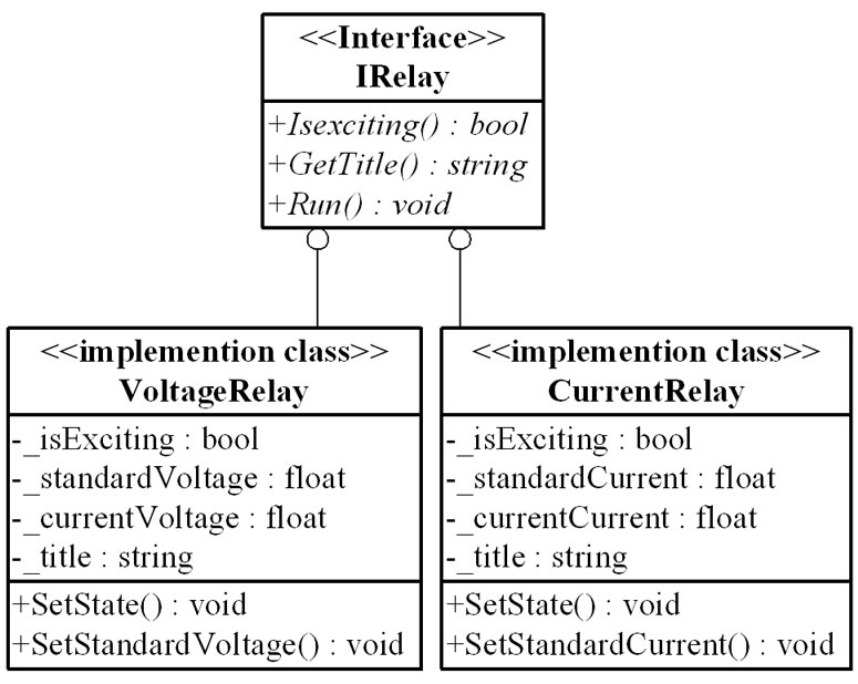
Figure 3. The class diagram of the contact.
The line is a special user control, connects two user controls, which are the member variables of the line: control1 and control2.These two member variables are also used in the all paths searching algorithm, as demonstrated in Section 4.
Besides the graphical interface of the circuit elements, the edit function for LD is also presented, of which the class diagram is shown in Figure 4. It is developed based on the command pattern, which encapsulates the detail of processing the messages. The functions of the controls such as adding, copying, cutting, moving and plastering can be performed through the menu or the shortcut keys. The function Add() of the menu is to add the user controls to the panel. Clicked() is to select an user control and generates the corresponding instance of the Command subclass, then call the function Execute() and sends the requirements to the control, which determines what to do. As mentioned above, based on the Command pattern, the details of the execution after sending a message is transparent for the menu.
Figure 5 shows the graphical interface corresponding to Figure 1, The right part of the interface is the library of circuit elements. After designing the interface, the control function of LD should be implemented, as presented in Section 4.