Design and Modeling of Electromagnetic Impedance Surfaces to Reduce Coupling between Antennas ()
1. Introduction
During last decade, the process of development of radio electronics, radio location, radio navigation, and radio communication worldwide was characterized by the following basic tendencies: technical realization of enhanced physical effects and technical solutions, aspiration to accomplish transmission and information processing in real time with the broad use of computers, and the expansion of the applications solved by technology. As a consequence, despite micro-miniaturization of radio electronics facilities (REF), the volume occupied by such equipment on mobile and stationary objects is increasing [1,2]. The progression of these modern trends is vitally necessary, but it aggravates even more the serious problem of the provision in radio engineering complexes (REC) of electromagnetic compatibility, which is understood as the ability of REF and REC to function together with limited degradation of their own essential parameters and features.
Practically, it is often required to provide significant decoupling between the receiving and transmitting antennas, located on a common surface at a small distance from each other. One of the most well-known ways to reduce coupling between antennas is the application of electromagnetic bandgap (EBG) structures [3-8]. The EBG structures have received increased attention in recent years [9] in the areas of the microwave application. For example, a corrugated metal surface may be viewed as a structure consisting of infinitely many identical cavities, each having an aperture that is open to the air half-space. The EBG property emerges by virtue of periodic reactive loading of the guiding structure. As shown in papers [10-13], the most effective solution to the problem of providing minimum coupling between antennas is to present and resolve inverse problems of electrodynamics.
In this paper, we re-visit the bandgap structure and present another interesting mathematical model for designing the structure and suppressing surface waves on metals. In addition, we examine the possibility of reducing the coupling between antennas located on the plane, using an inhomogeneous synthesized impedance. In particular, we investigate the design problem of the impedance surface when an infinite thread of in-phase magnetic current is located above the plane at a certain height, and also the case with its location right on the impedance surface. Finally, the behaviors of the complete field on the impedance surface and the decoupling level between antennas are also investigated.
The paper is organized as follows: in Section 2, we consider a solution to the problem of synthesis of an inhomogeneous impedance plane by a fixed reflected field.
A solution to the problem of coupling of antennas on an impedance plane is given in Section 3, and numerical results are discussed in Section 4. Finally, Section 5 is devoted to conclusions.
2. Design of Impedance Surface@NolistTemp#
2.1. Statement of the Design Problem
First, we consider a solution to the two-dimensional design problem for the arrangement shown in Figure 1. Above the plane , there is an infinite thread of in-phase magnetic current
  located at the height
 . On the surface
 , the boundary impedance conditions of Shukin-Leontovich are fulfilled:
 , (1)
, (1)
where  is the unit normal to the
  plane,
  is the surface impedance,
  is the electric field, and
  is the magnetic field.
It is necessary to determine the dependence of the passive impedance  on the surface S. Once Z(x) is obtained, the complete field in the upper space is found, and then the degree of decoupling between antennas can be obtained.
2.2. Solution of the Design Problem@NolistTemp# To obtain a solution to the problem, we introduce an orthogonal coordinate system in such a way that the plane

coincides with the impedance plane. Then, axis

is directed parallel with the thread of the current, as shown in
Figure 1. Further, we present the fields

and

on the surface as a sum of the incident and the reflected fields, respectively;
 , (2)
, (2)
where  and
and  are reflected fields,
  and
and . Here,
  is the ze-

Figure 1. Geometry of the design problem. The magnetic current Jm·ex is located at the height h.
roth-order Hankel function of the second kind,  is the wave number,
  is the wavelength,
  is the imaginary unit,
  is the characteristic resistance of free space,
  , and
, and  is the first order Hankel function of the second kind.
The reflected field can be written as a sum of the reflected field  in the fixed horizontal direction and the mirror-image field
  with unknown amplitude [13]:
 and
and where
where  and
and  are field vector components of an imaginary mirror source,
  and
and  are field vector components of the given reflected fields. The solution to the design problem given in this paper differs from the solution in [13] by the fact that there is no supposition of a large value of the distance
 , since the solution of reducing coupling between antennas in close proximity is of primary importance. The sense of this representation will become clear with further observation.
We now consider the analytical presentation of the distributed field on the  plane. As long as the amplitude of the plane wave does not vary along the direction of its distribution, then for the reflected field in the direction
 , it is possible to write:
 , (3)
, (3)
where  is the distribution of the scattered field on the surface
 . We represent the mirrorimage field on the impedance plane as the following way:
 where
where  is the constant amplitude. Then, the summative magnetic field on the surface
  can be written
 , (4)
, (4)
where . From the first Maxwell equation, neglecting the derivative multiplier
  and
and , we obtain for
  normalized on
 :
:
 (5)
(5)
where . As a result, for the required impedance normalized on
 , we also have:
 (6)
(6)
where  and
and . In the general case, the resulting correlation gives the dependence of the passive impedance which gives a real part that can acquire positive as well as negative values.
Next, let us consider the design problem of the purely reactive impedance . Presenting the correlation of Equation (6) as a real and imaginary part, we can obtain the condition of feasibility of purely reactive impedance:
 (7)
(7)
An additional degree of freedom in the form of a mirror-image field  gives an opportunity to realize the impedance structure with
  [13]. In this case, it is possible to find the impedance in the elegant form:
 , (8)
, (8)
where  and
and  is an angle of reflection. When the source of the field in Equation (6) is located right on the impedance surface
 , which provides a completely normal (at the angle
 ) reflection of the incident wave (without a mirror-image,
 ), the required impedance can be expressed:
 , (9)
, (9)
where  and
and . From the condition of purely reactive impedance feasibility
 it is not difficult to find the variation of the wave reflected from the inhomogeneous impedance plane,
 :
:
 , (10)
where . In this case, the impedance can also be found from a straightforward expression:
 , (11)
where ,
, 
and  are the zeroth and first-order Bessel functions, respectively, and
  and
and  are the zeroth and firstorder Neumann functions, respectively.
3. Model Analysis
The fact that variation of the surface impedance causes radiation of energy can be used to increase the decoupling between antennas, as well as to reduce the backscattering of the antennas. An example of a similar application of the surface impedance appears in Figure 2. Here, the resulting surface impedances change sharply, which brings about considerable decrease in current (because of re-radiation and reflection) flowing beyond the edge of the aperture or arriving at the second antenna.
The general system studied in this section has two aperture antennas in the shape of the open ends of parallel-plate waveguides (transmitting and receiving ones) with opening sizes of a and b, which are located on the y = 0 plane at a distance L from each other. On the y = 0 plane, several boundary conditions of Shukin-Leontovich [Equation (1)] are fulfilled. To solve the problem of analysis, we use the Lorentz lemma in the integral form for each of the three areas: ,
,  , and
, and , shown in Figure 2, i.e., by defining the field excited in the upper half-space (region
 ), the radiating waveguide (region
 ), and the receiving (region
 ) waveguide [14]. Then we can obtain a system of integral equations relative to the unknown tangential components of the electric field on the surface (
 and
and ) by taking into account the boundary conditions on the surface of the impedance flanges and the equality of the tangential field components in the openings of the waveguides
( in
in ;
;
 in
in ):
):
 (12)
(12)

Figure 2. The general system studied has two aperture antennas in the shape of the open ends of parallel-plate waveguides (transmitting and receiving ones) with opening sizes of a and b, which are located on the y = 0 plane at a distance L from each other. The system is composed of three regions: V1, V2, and V3.
where the subsidiary magnetic fields ,
,  , and
, and  are solutions of the nonuniform Helmholtz equations for complex amplitudes of the vector potentials for regions
 ,
,  , and
, and , respectively. In this way, the fields in the opening of the antennas and on the impedance part of the flange can be found. From this, the minimum level of coupling between the two antennas can then be determined.
It is necessary to note that development of an algorithm for the mathematical model under consideration is based on the specifics of the electric field at the edges  and on the numerical solution of a system of integral equations through the KrylovBogolyubov method [15].
4. Results and Discussion@NolistTemp# From remarks made earlier, the synthesized impedance structure must provide the decoupling of aperture antennas located on the same plane. The height of such antennas above the plane equals zero. In practice, the problem of synthesis is solved in the absence of the second antenna.
We next study the behavior of the complete field  on the impedance surface as a function of its dimensions and the parameters,
  and
and . In Figure 3, we show a graph of the variation of the impedance distribution [Equation (8)] with the following parameters:
  and
and  (solid line),
  (dashed line),
  (dotted line). We see in Figure 3 that the impedance distribution which gives a nearly hyperbolic reactance is the one for the angle
 . For
. For , the reactance remains zero for most of the interval, and for
 , the reactance is only slightly below zero. At the end of the interval [0, 0.66λ], the curve is undefined (it becomes infinite) for
 .
.
Figures 4(a) and (b) show the dependence of , normalized relative to the field
  above an ideal conducting plane for fixed
 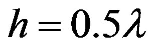 and various angles:

Figure 3. Variation of impedance distribution relative to Equation (8) for fixed h = 0.5λ and different angles: φ0 = 30˚ (solid line), φ0 = 45˚ (dashed line) and φ0 = 60˚ (dotted line). The length of the structure is L = λ. The impedance distribution which gives a reactance with a nearly hyperbolic character is the one for the angle φ0 = 60˚.
 (a)
(a) (b)
(b)
Figure 4. (a) Behavior of the complete field along the structure for fixed h = 0.5λ and various angles: φ0 = 30˚ (solid line), φ0 = 45˚ (dashed line) and φ0 = 60˚ (dotted line); (b) Behavior of the complete field along the structure for φ0 = 45˚ and h = 0.4λ (solid line); h = 0.5λ (dashed line) and h = 0.6λ (dotted line). The length of the structure is L = λ for both cases. The largest decoupling level is obtained with the parameters: φ0 = 60˚ and h = 0.5λ.
 (solid line),
  (dashed line) and
  (dotted line); and for the fixed angle
  with various values of the parameter,
  (solid line),
  (dashed line) and
  (dotted line), respectively. The length of the impedance structure is equal to
  for both cases. The results of calculations show that the best data (greatest decoupling) are obtained with the parameters
  and
and  when the impedance acquires the greatest capacitive value near the source of radiation. The greatest decoupling level is obtained with
  and
and . The synthesized impedance which gives appropriate results for increased decoupling should be taken into account, because it has a large negative value of the reactive part in close proximity to the antenna. This leads to the fact that the impedance practically creates an anti-phase field relative to the ideal conducting surface. As a result, all the energy of the electromagnetic field transfers into the energy stored around the antenna. The structure turns into a resonator without losses (for the reactive impedance), including radiation. As an example, Figure 5 shows the radiation patterns
  of the antenna located above the ideal conducting surface (dashed line) and the impedance surface (solid line) with the parameters:
  and
and . From the graph, it is apparent that decoupling is provided with reduction of the radiation field by 35 dB; i.e., a reduction of the main lobe of the radiation pattern.
Figure 6 shows the variation of the impedance distribution relative to Equation (11). The resulting impedance distribution is nearly flat (crossing zero at  and
and ), except for a sharp Fano-type variation at
 . The reactance reaches its minimum point with a capacitive reactance of 60, and sharply transitions to a maximum inductive value of 60. The behavior