Stretch Forming Simulation of Woven Composites Based on an Orthotropic Non-Linear Material Model ()
1. Introduction
Key criteria in developing new products include sustainability, recyclability and weight reduction. Published data [1] shows that the transportation industry accounts for 27% of the total Green House Gas (GHG) emissions solely in the United States. Results of analyses published by the institute of energy and environmental research [2] reveal that mass reduction of vehicles can substantially decrease CO2 emission and fuel consumptions. Thus, weight reduction in vehicles is regarded as one of the major priorities in the mass production industries such as automotive industry [3]-[5].
Woven Thermoplastic Composite Materials (WTPCMs) have shown great potential to be employed in the automotive industry due to their attractive properties including high specific strength, excellent impact energy absorption and balanced in-plane thermomechanical properties [6] [7]. Furthermore, they can be melted and re-shaped after initially consolidated, making them suitable candidates to address recyclability issues. However, the components currently made from these material systems are produced through labour-intensive, complex manufacturing techniques, such as moulding and hands lay-up of prepregs, resulting in very low manufacturing rates and expensive final products, hampering their wide spread applications. These manufacturing processes are not suitable for mass producing industries, where cost-effective products and high production rates are essential. Stamp forming of pre-consolidated woven composites is an efficient method for mass production of this material system. Recent studies show the great potential of producing complex components from woven composites through stamp forming [8]-[13]. However, successful adoption of stamp forming on woven composites necessitates a thorough study on the formability of this class of composite materials.
Formability of unconsolidated woven composites (prepregs) has been studied extensively [14]-[17]. However, forming behaviour of pre-consolidated woven composites through stamp forming is a current research initiative which needs to be addressed properly. To investigate formability of pre-consolidated woven composites under different forming conditions numerical simulation is an effective tool that can substitute cumbersome trial and error method in finding efficient production procedure. In the current study, an orthotropic material model based on the outcomes of characterisation experiments on a woven self-reinforced polypropylene composite (SRPP) is developed within an incremental deformation theory framework. The developed model was implemented into a Finite Element Analysis (FEA) software program (ABAQUS/Implicit solver) through a User-defined Material subroutine (UMAT). The numerical simulation predictions were verified against experimental results on the strain evolution at the pole of different samples. The combined effects of samples’ aspect ratios and forming parameters, including in-plane material stiffness and contact conditions, on the formability of a woven composite were elucidated. It was shown that the main forming parameters are dependent to the aspect ratio of a woven composite. The proposed nonlinear material model showed high capacity in predicting formability of a woven composite during rapid manufacturing processes and therefore offers good potential to be employed in the process of manufacturing industrial components.
2. Experimental Procedure
2.1. Material System
The pre-consolidated sheets of a multilayered 2/2 twill weave self-reinforced composite (SRPP) employed in the current study was manufactured by OCV reinforcements Co. [18] with 0.9 gcm3 volumetric density. Both reinforcements and the matrix were manufactured from a highly oriented semi-crystalline polypropylene polymer, making the final product to be completely recyclable. The woven fabric is manufactured from PP copolymers, made of two structurally different concentric cylinders of PP: a core made of α-PP polymer covered by b-PP polymer as the skin, in which the former has significantly higher melting temperature than the latter. Applying sufficient pressure and heat to the composite prepregs melts the skin of PP copolymer and constructs the matrix by embedding the unmelted b-PP reinforcement (selectively melting process). After cooling period, the consolidated multilayered SRPP composite sheets are produced.
2.2. Geometry of Specimens
In the current study, SRPP specimens with different aspect ratios (width-to-length ratios) were employed to characterise the woven composite and to study its forming behaviour at room temperature through two different sets of experiments:
1) Characterisation specimens: rectangular SRPP samples possessing 200 mm ´ 20 mm ´ 1 mm (length, width and thickness) dimensions were employed to characterise the composite material through uniaxial extension and bias extension tests. The test procedure followed ASTM D3039 standard as the standard test procedure for characterisation of polymer matrix composites. Specimens possessing [0˚, 90˚] fibre orientations were used in uniaxial extension tests to calculate longitudinal stiffness (Young’s modulus or E) and Poisson’s ratio (PR) of SRPP and samples with [−45˚, +45˚] fibre orientations were employed to measure the shear stiffness (G) of the SRPP composite through the bias extension test.
2) Stretch forming specimens: These specimens were cut-out from initially circular specimens of 200 mm in diameter. The samples’ widths (W in Figure 1) varied between 12.5 mm to 200 mm. The thickness of samples was 1 mm. General dimensions of SRPP specimens are shown in Figure 1. Each specimen is depicted by WN parameter in which N exhibits the width of the sample. For example, W50 and W200 represent a semi-rectan- gular specimen with 50 mm width and a full circular specimen with 200 mm diameter, respectively.
2.3. Experimental Equipment and Procedures
Two different experiments were conducted to develop a nonlinear material model and to evaluate the accuracy of the numerical model in predicting the stretch forming behaviour of SRPP composite:
1) Characterisation experiments: Two sets of experiments were conducted to characterise the SRPP composite including uniaxial and bias extension tests. The former was employed to characterise composite mechanical response to unidirectional loadings along the fibres, to calculate modulus of elasticity as a function of longitudinal strain and to evaluate Poisson’s ratio (PR) of the woven composite. The latter was designed to characterise the shear stiffness of the material by uniaxially extending [−45˚, +45˚] SRPP specimens in a bias extension test. The equipment included a universal testing machine (INSTRON 8874) to extend SRPP samples and to measure the force by a load cell and a CCD camera for recording deformations and calculating strains during deformations.
2) Stretch forming experiments: This set of experiment was designed and conducted on a variety of [0˚, 90˚] specimens to study their forming behaviours under different forming paths specified by the ratio of minor to major strains. Forming equipment included: a custom-built press with 300 kN capacity, a hemispherical punch, an open die with a built-in lock ring to enforce boundary conditions, a blank holder system, and two CCD cameras installed beneath the open die to measure strains and their evolutions during forming. The configuration of stretch forming equipment is shown in Figure 2. Strains were measured by an in-situ non-contact measurement system (the ARAMIS). The ARAMIS system was constructed of two high speed, high resolution CCD cameras capable of capturing images during deformation of a specimen to facilitate continuous tracking of displacements and calculating strains through deformation kinematics. In both experiments, the ARAMIS was set to capture deformations with the rate of 20 fps (frames-per-second). The cameras were positioned beneath the open die by an adjustable tripod, facing toward the painted surface of the specimen during forming (Figure 2). More details of the ARAMIS system and the implemented algorithm for calculation of strains can be found in [19].
3. Results and Discussions
3.1. Development of the Material Model
The characterisation experiments conducted on [0˚, 90˚] and [−45˚, +45˚] SRPP specimens revealed the nonlinear response of the woven composite to external loadings. The full characterisation of the woven SRPP required the definition of three different stress and strain dependencies: correlation between longitudinal stress and strain, longitudinal to transverse strains dependency and shear stress-strain behaviour. The outcomes of charac-
terisation experiments are depicted by the following equations:
 (1)
(1)
 (2)
(2)
 (3)
(3)
In the above equations, the parameters are defined as follows: A = −18.5E6, B = −25.2, c = 14188.75, d = 0.00841, F = 18.5E6, M = 0.052, N = 0.0043, p = 1.08, q = 0.009, L = −0.056, R = 117.8, S = −11.6, t = 28.35 and H = 11.6. The highly nonlinear nature of these relations necessitates application of an incremental deformation theory to effectively capture complex forming behaviour of SRPP as follows:
 (4)
(4)
 (5)
(5)
 (6)
(6)
These equations yield the following material properties for the SRPP woven composite:
 (7)
(7)
 (8)
(8)
 (9)
(9)
Subsequently, the stress and strain tensors can be coupled together through the following plane stress orthotropic material model:
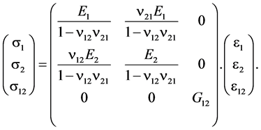 (10)
(10)
In this equation, s1, s2 and s12 depict different components of the Cauchy’s stress tensor including normal stress along 1 and 2 axes and in-plane shear stress. e1, e2 and e12 represent normal strains along 1, 2 and in-plane shear, respectively. E1 and E2 depict Young’s modulus along 1 and 2 axes, while n12 and n21 are the two Poisson’s ratios of the SRPP caused by stretching the specimen along the first axis depicted by the first subscript on the induced strain along the transverse axis, shown by the second subscript. The stiffness matrix of the woven composite was considered asymmetrical based on the following reasons: 1) E and n are both functions of strain. During each increment, the induced strains in 1 and 2 axes are not necessarily identical (depending on the width of the sample and enforced boundary conditions). Therefore, E and n along these two directions possess different values during different stages of deformation. 2) Existence of a strain potential function during a linear, small deformation process guarantees symmetrical properties of the material’s stiffness matrix. However, during stretch forming of a SRPP composite, large, non-linear deformations occur.
3.2. Stretch-Forming Studies
A total of 16 different SRPP specimens with different aspect ratios were stretch formed by the hemispherical punch until they fractured. The induced strains on the surface of SRPP samples were measured by the ARAMIS system. Principal strains were continuously calculated during each deformation increment. The ratio of minor to major strains (SR) was calculated to determine the induced deformation modes at the pole of specimens (The intersection of the two symmetry axes of the specimen). These deformation modes varied between the following regions: SR = −0.5 depicting uniaxial extension mode, SR = 0 exhibiting plane stress deformation and SR = +1 showing biaxial stretch.
Stretch forming simulations was conducted by the ABAQUS/implicit solver. The developed orthotropic material model was implemented into the ABAQUS by considering the plane stress condition governing stretch forming of thin SRPP blanks. Geometrical modelling of stretch forming experiment was accomplished through the ABAQUS Graphical User Interface. Four main parts were modelled within the ABAQUS/CAE (Figure 3): a hemispherical punch, an open die, a blank holder and the SRPP specimen. The first three components were modelled as 3D analytical rigid shells. The SRPP blank was modelled as a deformable 3D surface and was discretised by S4R5 thin shell elements to effectively capture bending phenomenon during stamp forming.
This type of shell element enforces Kirchhoff’s thin shells theory during forming of the composite. A total of 5000 to 10000 elements were used to discretise the blanks depending on their size. The numerical simulation was accomplished through three general steps: 1: The blank was positioned on the die and a normal traction force was applied to the semi-circular edges of specimens (Figure 1). This step was incorporated to simulate clamping or initial stretching of the blank due to local bend-unbend deformations applied by the lock ring embedded in the die system on samples 2: Both semicircular edges of the blank were fixed in the pre-stretch position and a normal pressure was applied on its flange areas through the blank holder 3: Initially, the punch was moved slowly toward the blank to stabilise the contact between the punch and the blank, prohibiting severe convergence issues due to local instabilities such as chattering. Afterwards, the punch was moved downward with a realistic forming speed (10 mm/s) to deform the blank until depth of failure specified by experimental outcomes.
The friction coefficient between blank holder-blank, die-blank and punch-blank pairs was set between 0.3 - 0.5. The contact between contact pairs was established through the master-slave approach with a surface-to- surface contact reinforcement. A linear penalty method was reinforced to the normal contact condition to prevent penetration of the contact pairs into each other. A general stabilisation procedure was enforced to address convergence issues during contact. To minimise the numerical errors, the ratio of the dissipated energy during contact and the overall energy required for forming was kept below a critical value.
![]()
Figure 3. Modelling of Stretch Forming Components Assembly in the ABAQUS.
Figure 4 compares the experimental outcomes and the numerical predictions on the strain path of different specimens at the pole.
The nonlinear strain path, evident in all specimens except for W200, is caused by different phenomena: 1) fixing merely the circular edges of specimens in the lock-ring causes a stretch and a contraction along the length and the width of the specimen due to Poisson’s effect, respectively 2) Establishment of initial contact between punch and the blank causes a local biaxial stretch in the pole of samples 3) Increase of forming depth changes biaxial stretch mode to another deformation mode governed by the aspect ratio of the sample 4) Gradual conformation of the blank to the punch geometry causes evolution of friction condition by variation of normal pressure and an asymmetrical contact surface along warp and weft directions (or along principal directions).
The FEA predictions demonstrate a similar trend with experimental outcomes during all stages of deformation. These results prove the high accuracy and reliability of the implemented numerical model for a woven composite during stretch forming condition. Both experiment and numerical simulations show the dependency of strain path to the aspect ratio of specimens: W25 and W50 demonstrate uniaxial and plain strain deformation modes, respectively. Increase of the specimens’ widths causes the deformation mode to shift toward biaxial stretch until W200 which exhibits SR of +0.95. The small deviation of W200 strain ratio from a complete biaxial stretch is due to the friction between the sample and the punch.
3.3. Effects of Different Parameters on the Strain Path
Experimental and analytical investigation on stamp forming of woven composites is complicated, time consuming and challenging due to the highly complex nature of contact condition between the punch and the blank, nonlinear mechanical response of woven composites to external loadings and complex coupling between different forming parameters. Employing a macro-mechanical numerical model facilitates analysis of different parameters on the formability of the woven SRPP efficiently by avoiding incorporation of complex interactions within the weave structure of the composite. Three specimens are selected (W25, W100, W150 with [0˚, 90˚] fibre orientations) and the effect of different mechanical properties and contact conditions on the strain path are studied.
The effect of friction condition on forming behaviour of a woven composite is elucidated in Figure 5. High and low friction conditions depict a friction coefficient of 0.1 and 0.9 between punch and the blank. The effect of friction condition on different regions of strain path is not identical. In wider specimens, the strain path does not change noticeably and the friction merely affects the maximum strains induced in the specimen: higher friction results in a more rigid body motion in the region around the pole, resulting in a decrease of induced strains. Lower friction causes a larger strain at the pole, causing more deformation on regions surrounding the pole. In wider specimens, increase in friction coefficient redistributes surface strains and decreases the maximum strain at the pole. In narrower specimens, the change in strain path is more noticeable. Generally, higher friction causes
![]()
Figure 4. Comparison between predicted strain path at the pole of different specimens by experimental and numerical simulations.
![]() (a)
(a)![]()
![]() (b) (c)
(b) (c)
Figure 5. Effect of changing friction coefficient on strain path at the pole.
the strain path to shift toward the plane strain by counteracting Poisson’s effect and hampering development of the negative minor strain. Friction condition only affects maximum induced strain during stretch forming of wide specimens but results in a major shift of the strain path in narrower samples due to non-proportional contact surface along warp and weft directions.
Figure 6 illustrates the effect of composite’s stiffness on the forming path. High and low stiffness of the
![]() (a)
(a)![]()
![]() (b) (c)
(b) (c)
Figure 6. Effect of changing Young’s modulus on strain path at the pole.
material differs by 30% compared to the original SRPP Young’s modulus. In narrow specimen, the effect of this change on the induced deformation mode is negligible. However, in wider specimens, the increase of stiffness causes a shift toward plane strain deformation mode with a decrease in principal strains for an identical forming depth. The noticeable effect of changing stiffness in different specimens is the length of pre-stretch deformation stage. This stage of forming process is a force-control process in contrast to other stages with a more displacement-control nature. Generally, changing the Young’s modulus within the realistic range of SRPP elasticity modulus does not show a prominent effect on the strain path of specimens, specifically in narrower specimens. Increasing the stiffness in wide specimens shows some local effects on the strain path, although the final gradient of the strain path seems to be identical.
Figure 7 elucidates the effect of PR on the strain path of different samples possessing different aspect ratios. The high and low PRs are different by 50% compared to original values. In narrow specimens, variations of PR cause a noticeable shift of the strain path. Decrease of the PR results in a more plane strain deformation mode, while increase of PR causes a shift toward more negative minor strains, e.g. shear deformation mode. However, in wider specimens the contact area along both longitudinal and transverse axes, e.g. warp and weft orientations, increases significantly. The change of contact area diminishes the effect of PR on the strain path due to the synergy between friction force and PR. Higher PR shifts the strain path of wider specimens toward negative minor strain or plane strain deformation mode, while lower PR shifts it toward biaxial stretch mode. These results reveal the complex effect of changing PR in the forming behaviour of a woven composite and its sensitivity to size effect.
Effect of shear stiffness on the strain path of woven composites, as shown in Figure 8, is probably the most
![]() (a)
(a)![]()
![]() (b) (c)
(b) (c)
Figure 7. Effect of changing Poisson’s ratio on strain path at the pole.
noticeable, yet non-intuitive phenomenon during stretch forming of a woven composite with [0˚, 90˚] fibre orientations. Intuitively, the shear stiffness should not have a remarkable impact on the deformation of a [0˚, 90˚] specimen during stretch forming, due to the fact that shear strain in these specimens should be very low. The numerical results show the validity of this hypothesis in narrow specimens. However, the forming results on wider specimens elucidate the significant impact of shear stiffness on the strain history. Decrease of shear strain shifts the strain path toward plane strain deformation mode, while increase of shear stiffness results in a more biaxial stretch deformation mode. Decreasing the shear stiffness causes a more uniform strain distribution on the surface of specimens in lower forming depths:
For the same forming depth, the maximum principal strain at the pole decreases, delaying onset of failure in the woven composite.
Figure 9 more clearly reveals the dependency of fibres’ strains at the pole of a typical specimen (W100) to the shear stiffness of the specimen which can be correlated to the shear strain evolution at regions located along +45˚ and −45˚ orientations. The numerical results clearly show that once shear strain at ±45˚ locations starts to rise, the major strain at the pole decreases and the regions possessing maximum major strain spreads over a larger surface area around the pole. These observations lead to a more profound understanding of forming of a woven composite: Initially, the punch contacts the blank at the pole and deformations occur locally, affecting a very small region around the pole (Figure 9(a)). Other areas on the blank move downward with the punch following a rigid body motion, without experiencing noticeable normal strains. At a specific forming depth, determined by the shear stiffness of the woven composite, regions located along ±45˚ directions experience high shear strains and less localised maximum strain at the pole (Figure 9(b)). The contact surface between the blank
![]() (a)
(a)![]()
![]() (b) (c)
(b) (c)
Figure 8. Effect of changing shear stiffness on strain path at the pole.
and the punch increases simultaneously. The blank starts to conform to the punch geometry further once the shear strains at ±45˚ areas increases. This is highlighted by a change in the strain path of the sample. During the final stages of deformation, the maximum strain moves completely from the pole to ward areas located along ±45˚ directions, the shear strain increases significantly and the blank conforms completely to the punch surface (Figures 9(c-c) & 9(c-d)).
4. Conclusion
Characterisation experiments were conducted on a pre-consolidated woven self-reinforced polypropylene composite (SRPP) to elucidate in-plane material properties including Young’s modulus, Poisson’s ratio and shear stiffness. These data were employed to construct an asymmetric orthotropic material model employed in a numerical simulation to predict stretch forming behaviour of the composite. Subsequently, stretch forming experiments were conducted on different SRPP specimens by a hemispherical punch. The induced strains during forming were continuously measured to elucidate forming behaviour of the SRPP under different forming modes. The match between the numerical simulation results and the experimental outcomes on the strain path at the pole of specimens were satisfactory. Then, the developed finite element model was employed to investigate the effect of different parameters on the forming behaviour of woven composites. All major variables showed sensitivity to the aspect ratio of the samples in changing strain path at the pole. These variables included material properties and friction condition. It was elucidated that in narrow specimens, the Poisson’s ratio and friction coefficient are the most influential parameters on the strain path and therefore on the formability of the woven composites. In wide specimens, the shear stiffness and Young’s modulus are more effective parameters in the formability of the composite than others. It was revealed that the shear stiffness of a [0˚, 90˚] woven composite
![]() (a)
(a)![]() (b)
(b)![]() (c)
(c)
Figure 9. Effect of shear strain on the evolution of major strain and forming profile of W100.
has a significant effect on developing a more uniform surface strain and therefore the enhanced formability of the woven composite.