Alternative Approaches for Distinguishing between Faults and Inrush Current in Power Transformers ()
1. Introduction
Power transformers are one of the most important elements in power systems. Therefore, the protection of power transformers and the prevention of tripping power transformer unnecessarily due to inrush current are crucial for the continuity of the power supply. Inrush current is drawn by the transformer when it is energized during commissioning, testing, or when it is connected to the network after maintenance. Inrush current is very high in magnitude compared to the normal magnetizing current and to the rated current of the power transformer which might reach hundred times the normal magnetizing current and few times the rated current. Also the time duration of the inrush current before reaching its steady state value—called the magnetizing current—is very small normally in mill seconds. In normal operation, the power transformer draws few amperes for magnetizing its core. But, when the power transformer is energized it draws an inrush current. Such high current might leads the protective relay system to trip the power transformer unnecessarily. Therefore, many methods are used to prevent the different protective relaying schemes from tripping the power transformer unnecessarily due to the inrush current. These methods depend on the knowledge of the inrush current waveform characteristics and the difference from the normal internal fault current. Modern means of restraining differential relays during magnetizing inrush current are two methods: 1) by recognizing inrush current from the wave shape of a differential current either indirectly (harmonic analysis) or directly (waveform analysis) [1] -[3] ; 2) by calculating—on line—one or more of the power transformer model elements (model analysis).
1.1. Inrush Current Characteristics
Power transformer exciting current at steady state causes current to flow in protective relay but it is so small under normal load conditions that the protective relay has no tendency to operate. However, any condition that calls for an instantaneous change in flux linkages in a power transformer will cause abnormally large magnetizing currents to flow, and these will produce an operating tendency in protective relays.
The largest inrush current and hence the greatest relay operating tendency occur when a power transformer has been completely de-energized and then a circuit breaker is closed, thereby applying voltage to the winding on one side (normally supply side) with the winding on the other side still disconnected (normally the load side). The inrush current might reach 50 times the normal exciting current and few times the rated current of the power transformer. The inrush current starts very large and it decays in mill seconds to its steady state value. The inrush current [4] is composed of harmonics of multiples of the fundamental frequency as shown in Table1
The second harmonic is very significant where it represents 63% of the amplitude of the total inrush current. The fault current is composed of the fundamental frequency and it lasts until the fault is removed. The magnitude of the fault current depends on the type of the fault and location. Protective relays schemes used to prevent relays from tripping power transformers during inrush current based on the knowledge of the nature of the inrush current signal and its difference from the fault current where power transformer should be tripped.
Magnetizing inrush current in transformers results from any abrupt change of the magnetizing voltage. Generally, the magnetizing inrush current may be caused by the following [5] [6] :
• Energizing a power transformer;
• Occurrence of an external fault;
• Voltage recovery after clearing an external fault;
• Change of the character of a fault (for example when a phase-to-ground fault evolves into a phase-to-phaseto-ground fault), and
• Out-of-phase synchronizing of a connected generator.
Since the magnetizing branch representing the core appears as a shunt element in the transformer equivalent circuit model, the magnetizing current upsets the balance between the currents at the transformer terminals, and is therefore experienced by the differential relay, the main protection of power transformers, as a “false” differential current. The relay, however, must remain stable during inrush conditions. In addition, from the standpoint of the transformer life-time, tripping-out during inrush conditions is a very undesirable situation since breaking a current of a pure inductive nature generates high over voltage that may jeopardize the insulation of a transformer
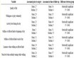
Table 1 . Amplitude of inrush current harmonics.
and be an indirect cause of an internal fault.
1.2. Inrush Current Due to Energizing a Transformer
Initial magnetizing due to switching a transformer in is considered the most severe case of an inrush. When a transformer is de-energized (switched-off), the magnetizing voltage is taken away, the magnetizing current goes to zero while the flux follows the hysteresis loop of the core. This results in certain remnant flux left in the core. When, afterwards, the transformer is re-energized by an alternating sinusoidal voltage, the flux becomes also sinusoidal but biased by the remanence. The residual flux may be as high as 80% - 90% of the rated flux, and therefore, it may shift the flux-current trajectories far above the knee-point of the characteristic resulting in both large peak values and heavy distortions of the magnetizing current.
Figure 1 shows a typical inrush current waveform. The waveform displays a large and long lasting dc component, is rich in harmonics, assumes large peak values at the beginning (up to 30 times the rated value), decays substantially after a few tenths of a second, but its full decay occurs only after several seconds (to the normal excitation level of 1% - 2% of the rated current). In certain circumstances, some small changes of the excitation current are observable even minutes after switching a transformer in [7] .
The shape, magnitude and duration of the inrush current depend on several factors.
• Size of a transformer.
• Impedance of the system from which a transformer is energized.
• Magnetic properties of the core material.
• Remanence in the core.
• Moment when a transformer is switched in.
• Way a transformer is switched in.
The highest values of the inrush current occur when the transformer is switched in at the zero transition of the winding voltage. It is approximated that every 5th or 6th energizing a power transformer result in considerably high values of the inrush current [8] .
• 1.3. Difficulties in Differential Protection for Power Transformers [9]
• Mismatch between the CT ratios and the power transformer ratio.
• CT saturation.
• Variable ratio of the power transformer caused by a tap changer.
• Phase shift between the power transformer primary and secondary currents for delta-wye connections.
• Magnetizing inrush currents created by transformer transients because of energization, voltage recovery after clearance of an external fault, or energization of a parallel transformer.
• High exciting currents caused by transformer over excitation.
The relay percentage restraint characteristic typically solves the first two problems. A proper connection of the CTs or emulation of such a connection in a digital relay-auxiliary CTs historically provided this functionaddresses the phase shift problem. A very complex problem is that of discriminating internal fault currents from
the false differential currents caused by magnetizing inrush and transformer over excitation.
Figure 2 shows a typical differential relay connection for power transformer protection. High demands are imposed on power transformers protection differential relays. The requirements include dependability (no missing of operation), security (no false tripping), and speed of operation (short fault clearing time). Numerical relays are capable of performing sophisticated signal processing, enable the relay designer to re-visit the classical protection principles, and enhance the relay performance, facilitating faster, more secure and dependable protection for power transformers [8] .
2. Desensitizing and Tripping Suppressor
This technique depends in its old version—desensitizing version—on the fact that inrush current duration is very short in hundreds of mill seconds therefore, blocking the protective relay system during this period usually for 0.2 seconds or more will often ride over the inrush period and the magnitude of inrush current will become small enough such that protective relay will not pick-up and will not trip the power transformer. One type of desensitizing equipment of this version consists of an under voltage relay with normally opened contacts and having time-delay pickup and reset; these contacts are connected in series with a low resistance resistor that shunts the operating coil of the differential relay in each phase as shown in Figure 3. When the power transformer is de-energized, the under voltage relay resets and its contacts closed and complete the shunt circuit across the operating coil of the differential relay [4] .
The under voltage relay will not pick up and open its contacts until a short time after the power transformer has been energized, thereby desensitizing the differential relay during the magnetizing inrush current period.
The later version of this technique—tripping Suppressor—is an improvement of the desensitizer. Three highspeed voltage relays, connected to be actuated by either phase-to-phase or phase-to-neutral voltages, control tripping by differential relays. If all three voltage relays pick up during the inrush period, a timer is energized that closes a normally opened contact in the tripping circuit of the differential relay after enough time delay so

Figure 2. Typical differential relay connection for power transformer protection.

Figure 3. Desensitizing equipment to prevent differential relay tripping on magnetizing inrush current.
that tripping on inrush current alone would not occur. But, for any fault that will operate the differential relay and also reduce the voltage enough so that at least one voltage relay will not pick up, tripping occurs immediately. In other words, tripping is delayed only for very low current faults that affect the voltage only slightly. Any external fault that lowers the voltage enough to cause a significant inrush current when the fault is cleared from the system will reset one or more of the voltage relays, thereby resetting the timer and opening the trip circuit long enough to assure that the protective relay will not trip the power transformer due to inrush current as a result of an external fault clearing.
But delay used by different means to prevent false tripping during inrush conditions either by disabling the relay for a given time when switching a protected power transformer in or used other techniques are being used in the past and they are not any more acceptable, especially for large power transformers.
3. Harmonic Current Restraint
The principle of harmonic-current restraint makes the differential relay self-desensitizing during the inrush current period, but the relay is not desensitized if a short circuit should occur in the power transformer during the inrush current period. This relay is able to distinguish the difference between the inrush current and the short circuit current by the difference in wave shape [4] . Inrush current is characterized by large harmonic components that are not noticeably present in short circuit currents as shown in Table1
Figure 4 shows how the relay is arranged to take advantage of the harmonic content of the current wave to be selective between faults and inrush current. The restraining coil (blocking coil) will receive from the throughcurrent transformers the rectified sum of the fundamental and harmonics components. The operating coil will receive from the differential-current transformer only the fundamental difference component of the differential current, the harmonics being separated, rectified, and fed back into the restraining coil. The direct current component, present in both inrush current and fault current, is largely blocked by the differential-current and the through-current transformers, and produces only a slight momentary restraining effect. The magnetizing inrush current appearing to a relay as the differential signal, displays certain amounts of higher harmonics. Generally, low levels of harmonics enable tripping, while high levels indicate inrush and restrain the relay. This method originates a whole family of algorithms using a variety of approaches in combining currents of the harmonics and the fundamental ones are:
In the simplest approach, the amplitude of the second harmonic in the differential current in a given phase is the combined harmonic signal, while the amplitude of the fundamental frequency component in the differential current in the same phase is used as the combined differential current.
Another approach is to use the RMS value for the combined differential current. When using this method criterion must be checked in each phase separately. Extra logic is needed to decide whether or not the entire threephase relay should get restrained if either one, two or three phases detect inrush conditions. The relay behavior under such circumstances may be flexibly shaped by using cross polarization or a cumulative (three-phase)

Figure 4. Harmonic current restraint differential relay.
second harmonic.
It is experienced, that the three phase harmonic restraint is more secure [8] . The cumulative restraint defines the combined currents as sums of the appropriate quantities over three phases.
Also, instead of the real RMS, only low order harmonics can be used. In such approach, the combined differential signal is composed. Where the highest harmonic measured (usually the fifth harmonic used for restraining the relay during stationary over excitation conditions).
Finally, a modern method used both the magnitude of the dominant harmonics compared to the fundamental frequency as used in old versions of this method in addition to the phase shift of these harmonics to the fundamental one. This method gives a more reliable criterion above the others in blocking the differential relay during inrush current case since it considers the drop of the second harmonic magnitude momentarily to less than 20% of its magnitude. Depending on the exact formula employed for the combined harmonic and differential signals, the setting assumes slightly different values. Generally, however, the setting is at about 0.15 - 0.20 (15% - 20%) [7] .
The harmonic restraint in general, regardless of the method of composing the combined harmonic and differential signals, displays certain limitations.
First, the estimator of the harmonic component (usually the second harmonic only) needs a certain amount of time for accurate estimation of the amplitude. Even if the harmonic is not present in the differential signal at all, the ratio of the harmonic current to the differential current is initially significantly overestimated (until the fault data fills out the estimator data window). This means that the harmonic restraint usually will not permit tripping for the time approximately equal to the data window length of the estimators (typically one cycle).
Second, in modern transformers the amount of higher harmonics in the magnetizing current may drop well below 10% (the second harmonic as low as 7%, while the total harmonic content at a level of 7.5%. Under such circumstances, the setting should be adjusted below 7%. This may lead, however, to delayed or even missing operations of the relay due to the harmonics in the differential currents during internal faults accompanied by saturation of the current transformers. Cross-restraint or time-controlled threshold provide only a partial solution to this problem.
Third, the second harmonic ratio may temporarily (for several cycles) drop below the safe 20% due to transients.
4. Waveform-Based Restraints
This method is a direct wave form analysis. It depends on the characteristics of the inrush current waveform and its difference from the fault current waveform. Fault current in general has a non decaying sinusoidal wave while inrush current has low and flat periods for a 1/4 cycle beside its peaks are of the same polarity and its value decays with time as shown in Figure 5.
Generally, there are two basic waveform restraining methods:
The first, and more common approach, pays attention to the periods of low and flat values in the inrush current. If the shape of the waveform is not flat and close to zero for more than 1/4 of the cycle then it is not an inrush current case.
The second algorithm pays attention to the sign of the peak values and the decaying rate of the inrush current. If any consecutive peaks has different polarities and displaced by a half cycle then it is not an inrush current case.
The main disadvantage of this algorithm is the need of cross polarization between the phases. Not always all three phases show the typical inrush uni-polar waveform. Also, during very smooth energization of a protected transformer (what may accidentally happen owing to the adequate relation between the switching angle and the remnant flux), this criterion will fail.
A considerable number of studies of detecting inrush currents have been proposed as follows. A method using the equivalent circuit of the power transformer [10] , a method observing the active power flowing into the transformer [11] , a method using artificial neural networks [12] , a method using a multi-criteria approach [13] , a method using the similarity between the wave forms of current and voltage [14] , a method using wavelet transformation [15] and a method based on the magnetization characteristics of the transformer core [16] .
These methods, among others, have been proposed as more reliable methods than the conventional method of using the second harmonic component.

Figure 5. Periods of low and flat inrush current.
Therefore, with the power transmission system becoming larger in both capacity and voltage, coupled with the wide spread use of underground cables, it produces a sizable amount of second harmonic current in the event of fault. The content of this second harmonic current can be comparable to that produced in the inrush current. So the differential scheme with second harmonic current restrained becomes unreliable for transformer protection [17] .
Modern transformers built with improved magnetic materials that have high knee-point, and therefore, their inrush current display a comparatively low amount of the second harmonic. Therefore, certain difficulties arise when protecting such modern transformers [1] [8] [18] .
It is also known that when the inrush current assumes large values, the amount of the second harmonic decreases [5] [6] .
5. Fictitious Equivalent Resistance Method
The family of model method approaches solves on-line a mathematical model of a fault-free transformer. Either certain parameters of the model are computed assuming the measured signals; or certain fraction of the terminal variables are computed based on all the remaining signals, and next compared to their measured counterparts [19] . In the first case, the values of the calculated parameters differentiate internal faults from other disturbances (including inrush conditions). In the second case, the difference between the calculated and measured signals enables the relay to perform the classification. These approaches call for voltages and currents at all the terminals to be measured.
5.1. Method of Modeling and Analysis
The starting point for analyzing the transients is the accurate representation of the transformers’ magnetic core. The model of the power transformer in this paper depends on Fitting Saturation and hysteresis via Arctangent Functions [20] . This method is an approximation of the transformer saturation curve. It is based on measurements of the magnetizing curve of the ferromagnetic material of the iron core of the power transformer. The analytical form of the saturation characteristic can be completely described by only three parameters. These three parameters are enough to take into account: the slope of the linear region of the saturation curve, the position of the knee, and the saturating slope.
For the transformer under study its parameters are [20] :


where c is the reciprocal of the slope of the linear region of the saturation curve, L1 represents the magnetizing inductance of the power transformer and Rw represents the no-load iron core losses.
Then the relation between the magnetizing flux linkage φ(t) and the magnetizing current of the power transformer im(t) is expressed by the following equation and as proposed in [20] .
 (1)
(1)
Arranging for φ(t) yields
 (2)
(2)
From Figure 6 the governing equations are
 (3)
(3)
where ω is the power angular frequency, and the phase angle α describes the switching time point. The special value α = 0 means transformer switching at the voltage zero crossing, whereas α = л/2 represents a switching at the peak of the supply voltage e(t).
 (4)
(4)
 (5)
(5)
Now, rearranging Equation (5);
 (6)
(6)
Also, rearrange Equation (3);
 (7)
(7)
Substituting Equation (6) into Equation (7) and arranging gives that
 (8)
(8)
Let us differentiate Equation (2) and substitute it in Equation (4)
 (9)
(9)

Figure 6. The sample transformer model circuit.
Substitute Equation (9) into Equation (6) gives
 (10)
(10)
5.2. Model Simulation Results
Solving the differential Equations (8) and (10) to find is(t) and im(t) using Runge-Kutta method with initial value is(0) = 0 and im(0) = 0. The solution for the above equations was written using MATLAB and the results were obtained for energizing the power transformer for a 60 HZ power network with Em = 156 v and carried out for both inrush and faulty cases.
The simulation carried out for different phase angles (α = 0˚, 45˚, 90˚) of the supply voltage e(t).
Case A: Energizing a Healthy Transformer (Inrush Current):
The results in Figures 7-9 are carried out for Rw = 400 Ω and time range 0 ≤ t ≤ 30 milliseconds.
In Figure 7 for α = 0˚ the current is(t) is unidirectional and reaches a maximum value of 23 A which is almost 9 times the steady state value (2.5 A). The waveform shows a high harmonic content. Both the flux φ(t) and the induced voltage v(t) are distorted.
In Figure 8 for α = 45˚ the three time waveforms of the current is(t), the flux φ(t) and the induced voltage v(t) shows almost the same level of harmonics content and distortion. But the current magnitude shows a lower value 15 A.
In Figure 9 for α = 90˚ the time waveform of the current is(t) still reflects the harmonics content and distortion and its peak value almost equals the steady state value 2.5 A. The flux φ(t) time waveform is sinusoidal, in


Figure 7. Energizing a healthy transformer at α = 0˚.
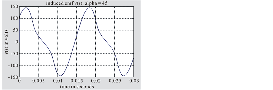


Figure 8. Energizing a healthy transformer at α = 45˚.
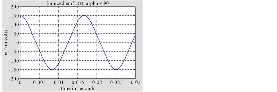


Figure 9. Energizing a healthy transformer at α = 90˚.
phase with is(t), and has no distortion or harmonics. While the induced voltage v(t) is sinusoidal, and 90˚ phase shifted with is(t).
From Figures 7-9 we notice the relation between the inrush current maximum magnitude is(t) and the phase angle α of the energizing voltage e(t). As α increases the magnitude of the inrush current is(t) decreases and the highest value of the inrush current occurs when energizing the transformer at α = 0˚.
Case B: Energizing a Faulty Transformer:
The results in Figures 10-12 are carried out for Rw = 0.02 Ω and time range 0 ≤ t ≤ 3 seconds. Time simulation increased to show the steady state value of the variables.
In Figure 10 for α = 0˚ the current is(t) reaches momentarily a value of 75 A (30 times the steady state value), and the DC-offset is very clear in the waveform. Finally the current settles down to 40 A. The waveform of the induced voltage v(t) shows a low magnitude as expected with a DC-offset and it settles down to 0.7 v. The flux φ(t) settles down to 0.38 wb.
In Figure 11 for α = 45˚, the current is(t) reaches momentarily a value of 62 A (25 times the steady state value), and the DC-offset is very clear in the waveform. Finally, the current settles down to less than 40 A. The waveform of the induced voltage v(t) shows a low magnitude as expected with a DC-offset and it starts with 1.5 v and settles down to 0.7 v. The flux φ(t) settles down to 0.38 wb.
In Figure 12 for α = 90˚ the current is(t) is sinusoidal with its peak value 38 A which is almost 15 times the steady state value. The waveform of the induced voltage v(t) is sinusoidal and in phase with the current is(t) with a low magnitude as expected of 0.75 v. The flux φ(t) is sinusoidal with a peak value of 0.004 wb.
From Figures 10-12 we notice the relation between the fault current maximum magnitude is(t) and the phase angle α of the energizing voltage e(t). As α increases the magnitude of the fault current is(t) decreases and the highest value of the fault current occurs when energizing the transformer at α = 0˚. The induced voltage v(t) is very low and close to zero as expected for a fault case.
5.3. Estimation of the Fictitious Equivalent Resistance Rw
The basic idea of the fictitious equivalent resistance method is based on calculation of a fictitious resistance Rw


Figure 10. Energizing a faulty transformer at α = 0˚.


Figure 11. Energizing a faulty transformer at α = 45˚.


Figure 12. Energizing a faulty transformer at α = 90˚.
from the power transformer no-load equivalent circuit in Figure 6. The value of Rw is between the power transformer resistance which is known and zero. If the resistance computed on line from the data representing the current passing through the power transformer is high and very close to the power transformer resistance, then the current represents an inrush current case which requires blocking the protective relay from tripping the power transformer. Otherwise, if the estimated resistance Rw is very small and close to zero then the current passing through the power transformer is a fault current case which requires the activation of protective relay to trip the power transformer.
The first derivative of the core flux can be obtained from Equation (2) and arranging we get Equation (11):
 (11)
(11)
Differentiating Equation (3) and substituting in Equation (11) we get:
 (12)
(12)
Calculation of Rw is done on line by solution of Equation (12) as an algebraic equation in variable RW.
All other quantities (a, b, c, L1, the value of the primary currents is,k and voltage ek as well as their derivatives are already known). Estimates for Rw can be computed iteratively on line. The estimated numerical value of Rw will determine whether these current and voltage samples are due to energizing a faulty transformer or resulting from inrush phenomena. The estimation of Rw will be continuously updated as new current and voltage samples arrive to be digitally processed and older values are deleted.
The first derivatives of e(t) and is(t) and the second derivative of is(t) are calculated as discrete values with a sampling rate h as follows:
 (13)
(13)
 (14)
(14)
 (15)
(15)
The estimation of the fictitious resistance Rw, from Equation (12), has been carried out iteratively for both the inrush current case and the faulty case for α = 0˚, 45˚, 90˚.
Case A: Estimating Rw for a Healthy Transformer (Inrush Current):
In Figures 13-15, the estimated values of Rw is plotted against their corresponding time points and also the average value of Rw is calculated and plotted. The contents of these plots are summarized in Table2 We notice that the estimated value of Rw for different α fluctuates close to the assumed value 400 Ω.
It is clear from Table 2 that’s the estimated value of Rw is close enough to the assumed value 400 Ω of the inrush current case and very far from its value for the fault current case 0.02 Ω.
Case B: Estimating Rw for a Faulty Transformer:
In Figures 16-18, the estimated values of Rw is plotted against their corresponding time points and also the average value of Rw is calculated and plotted. The contents of these plots are summarized in Table3 We notice that the estimated value of Rw for different α fluctuates close to the assumed value 0.02 Ω.
It is clear from Table 3 that’s the estimated value of Rw is close enough to the assumed value 0.02 Ω of the fault current case and very far from its value for the inrush current case 400 Ω.
Therefore, we can say safely that the estimated value of Rw can be used to discriminate between the inrush current case where the differential relay must be prevented from tripping the power transformer unnecessarily and the fault case where the differential relay is allowed to trip the faulty transformer.
6. Conclusions
1) The importance of reliable discrimination between large currents due to internal and external faults and those due to inrush current is pointed out.
Table 2. Maximum, minimum and average value of Rw for inrush current case.

Figure 13. Calculating Rw for energizing a healthy transformer α = 0˚.

Figure 14. Calculating Rw for energizing a healthy transformer α = 45˚.

Figure 15. Calculating Rw for energizing a healthy transformer α = 90˚.
2) The characteristics and nature of inrush current is explained thoroughly and compared to the fault current.
3) The Desensitizing and Tripping Suppressor method used to block differential relays from tripping power transformer due to in rush current is one of the oldest methods used. It basically has an enough time delay through restraining coil to disable the protective relay to let the inrush current reduces to a safe values then activates the protective relay system.
4) The Harmonic-Restraint method makes an advantage of the harmonic contents of the inrush current. The second harmonic is dominant in inrush current. Therefore, this signal is used as a preventing signal (blocking or restraining) of tripping since it indicates an inrush current case. This method depends on using the magnitude of
Table 3 . Maximum, minimum and average value of Rw for faulty case.

Figure 16. Calculating Rw for energizing a faulty transformer α = 0˚.

Figure 17. Calculating Rw for energizing a faulty transformer α = 45˚.

Figure 18. Calculating Rw for energizing a faulty transformer α = 90˚.
the fundamental frequency signal to operate the relay and the magnitude of the second harmonic-and other harmonics (the fifth harmonic) and features (phase shift)-to block the relay. Modern power transformers have lower values of the second harmonic and also due to transient its value might become small enough to give wrong indication to the relay system. The minimum time to allow tripping is one cycle which is the time needed to estimate the system harmonics. One cycle (0.02 seconds for 50 Hz systems) is considered long time for severe short circuit and might put the power transformer in risk.
5) A model for simulating the transients of both inrush and internal fault currents is applied to a case study based on a closed-form analytical representation of the transformer’s magnetization curve, its leakage inductance as well as the no-load losses.
6) The relationship between the inrush current and fault current maximum magnitudes and the phase angle α of the energizing voltage shows that the highest value of the inrush or fault current occurs when energizing the transformer at α = 0˚ while the lowest currents occurs at α = 90˚.
7) A procedure to distinguish between inrush and fault current is suggested and tested. It is based on estimating the value of the fictitious equivalent resistance Rw whose possible range is between zero and the value of the transformer’s resistance in its no-load equivalent circuit. Too small values of this resistance imply internal faults, whereas higher values describe situations involving inrush current.
8) The values of Rw estimated in this paper for different values of α and for both inrush and faulty cases are summarized in Table 2 and Table3 From these results it can be safely stated that the use of the suggested procedure can be used to recognize whether the current and voltage samples are describing a fault current or an inrush current.