Mechanical Properties for Reliability Analysis of Structures in Glassy Carbon ()
1. Introduction
Because of high radiation length and high temperature resistance, carbon and glassy carbon (GC) in particular are interesting materials in high energy physics applications where interaction particles with matter are expected. Glassy carbon is a material obtained by the pyrolysis at high temperature of a highly reticulated resin. Method of production can be found in ref. 2. This material is used for example for chemical applications, electrodes or MEMS. Nevertheless, GC is not commonly used for structural applications. The determination of the mechanical properties of this material is essential for the design and the analysis of performance and reliability of structures.
In the literature, microand nano-indentation tests are widely reported for the evaluation of the elastic properties and strength of the GC [3] -[6] . The Young’s modulus is derived from the penetration loading curves. Values in the range 21 GPa [3] -22.5 GPa [5] are given. Indentation methods address local near surface properties. A few authors refer to the bulk properties. A Young modulus of 28 GPa has been reported by Saika on GC obtained after pyrolysis of 2500˚C and tested with the resonance method [6] .
The determination of the strength is crucial for the reliability of a structure. The results found in the literature are usually based on a deterministic approach. Bullock and Kaae applied a statistical approach for GC plates obtained after pyrolysis at 1800˚C [7] [8] . 3 point bending tests were used and shape and scale parameters were around 6 and 104 MPa, respectively. No other statistical data are available for GC neither on other GC grade nor other test configurations (geometry or loading conditions).
The toughness is also an important property to evaluate the reliability of a structure, especially for a brittle material. The data in the literature confirmed the brittleness but had shown quite large scattering of the toughness in the range 0.58 - 1.18 MPa·m1/2 for GC treated at 2000˚C [6] [9] .
The effect of the heat treatment temperature (HTT) during the manufacturing process on the Young’s modulus and the flexural strength is not clear. Some authors have shown values that decrease when the heat treatment temperature increases [4] whereas others have shown a more erratic behaviour with higher stiffness and strength with HTT at 2000˚C [9] . It is therefore quite hazardous to apply data obtained from a different heat treatment process to another grade. The fracture toughness of GC slightly increases with the HTT [9] .
Similarly to the literature, data provided by different suppliers also exhibit large scattering. Therefore, it is mandatory for structural applications to well characterize the material. In the present study, two grades from HTW (Hochtemperatur-Werkstoffe GmbH, Thierhaupten, Germany) have been considered. Grade K is obtained after a heat treatment at 1000˚C whereas 2200˚C is used for the grade G. Chemical analyses have been done by Energy-dispersive X-ray spectroscopy. The material is composed of around 98% (weight) of carbon and 2% of oxygen. The strength of the GC grade G has been determined with a statistical approach for bending and compressive stress.
2. Experimental Procedure
2.1. Material
The glassy carbon studied has been produced by Hochtemperatur-Werkstoffe GmbH, Thierhaupten, Germany. The samples K and G have a maximum heat treatment of 1000˚C and 2200˚C, respectively.
Different geometries have been considered depending on the intended property measurement.
• Plates 70 mm long, 13 mm wide and 2 mm thick have been used for the determination of elastic properties.
• To avoid any defects induced by the preparation of the samples, rods, in grade G, of diameter 6 mm and a length of 50 mm and 15 mm have been used to measure the flexural and compression strengths, respectively. The surface of the samples is as received. For the flexural strength tests, the distance between the central supports is 25 mm whereas d, the distance between the outer supports, is 7.5 mm. Supports have fillet to not introduce stress concentration at these locations.
• Notched rods, in grade G, of diameter 6 mm and a length of 50 mm have also been used to estimate the toughness. A notch, with a depth around 0.05 mm, has been made with a diamond tooling. A CT specimen in glassy carbon has been machined with diamond tools. It consists in squared plates of 50 mm long side and 4 mm thick. An initial crack of 20 mm (10 mm with respect to the pulling axis) is done. The set-up, based on articulations in aluminium, avoids any bending on the specimen.
2.2. Elastic Modulus
The Young’s modulus and Poisson’s ratio have been determined by 4 point bending tests on plates. Strain gauges, oriented at 0˚ and 90˚ with respect to the plate axis, have been glued on the surface subjected to tension.
2.3. Strength
A statistical analysis based on the Weibull’s law has been done. The survival probability of a volume Ω described in the Weibull’s theory is given by:
 (1)
(1)
σeq stands for an equivalent stress that is usually considered for brittle material as the positive part of the principal stress. σ0 and m denotes the 2 parameters of the Weibull’s law, called scale and shape parameter respectively.
2.3.1. Flexural Strength of a Rod
It is assumed that the failure probability in the compressive zone is much lower than in the tensile zone. For the 4 point bending test, the equivalent stress reads:
• in the central region of length L:
• 
• between the supports separated by a distance d:

The bending stress σb is given by:
 (2)
(2)
with F the load applied to the set-up.
After integration on the sample geometry, the survival probability reads:
 (3)
(3)
The survival probability is estimated from the test results by two estimators:
 (4)
(4)
 (5)
(5)
with i the number of the test considering a ranking increasing with failure load. nt denotes the total number of tests.
The relationship between the survival probability and the loading force is given by:
 (6)
(6)
A linear regression is carried out. The slope and the ordinate at origin (y-intercept) lead to the determination of the two Weibull’s parameters.
2.3.2. Compression Strength
In this configuration, the stress is constant over the volume and the survival probability reads simply:
 (7)
(7)
2.4. Fracture Toughness
The fracture toughness has been estimated on grade G by two different methods: the first one based on a notched bar subjected to 4 point bending and the second on CT specimen.
Notched Rod
The fracture toughness of a notched rod under bending is given by Equation (8) with the corresponding geometry given in Figure 1:
 (8)
(8)
with

and c = b – 2a For this test, the toughness is derived from the maximum force by Equation (9):
 (9)
(9)
with α standing for the ratio between the crack length and the specimen width, w. b denotes the thickness.
3. Results and Discussion
3.1. Elastic Properties
The elastic mechanical parameters, namely the Young modulus and the Poisson’s ratio, obtained by 4 point bending on plates, are reported in Table 1 as well as the flexural strength.
These Young modulus measurements are significantly higher than values found in the literature and based on indentation method [3] -[5] . Contrary to the literature, no significant difference on the Young’s modulus has been observed between the two grades heat treated at two different temperatures (1000˚C and 2200˚C).
The Poisson’s coefficient are higher (~10%) than data measured by Zhao [9] . The same decrease between grades HTT at 1000˚C and 2200˚C is observed.
It is worth to note the dispersion and the low values obtained for the flexural strength. They are due to small chips observed after the sample cutting, even with diamond wire. Typical strain-stress curves for the flexural tests on the grade G and K plates are given in Figure 2 as well as the evolution of the Poisson’s ratio that is not constant at low strains.
3.2. Tensile Strength of Glassy Carbon
20 samples have been tested with a 4 point bending set-up. The results have shown an average flexural strength of 206 MPa with a standard deviation of 37 MPa. Conchoidal fracture of the specimens is observed.

Figure 1. Geometrical parameters of the notched bar.
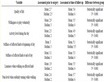
Table 1. Measures of the elastic properties of glassy carbon.
Statistical approach is used to represent the flexural strength. From Equation (6), a linear regression is carried out and leads to the determination of the two Weibull’s parameters (Figure 3). m and σ0 have been identified to 5.59 and 416 MPa, respectively, for the first estimator and to 6.33 and 375 MPa, respectively for the second estimator. This gives an average of 5.96 and 396 MPa for the shape and scale parameter, respectively. The shape parameter is in very good agreement with the value of 6 found in the literature whereas the scale parameter is higher in our results [8] .
A finite element model has been used to analyze the survival probability of the samples and validate the assumption for the stress field (equation section 1.3.1). A quarter of the sample geometry has been considered and is shown in Figure 4. The survival probability field is shown in Figure 4 as well. The size effect of the elements can be noted on the same figure.
The evolutions of the survival probability as a function of the flexural load for the analytical study, finite element analysis and experimental tests are compared in Figure 5. They are all in good agreement even if the ana-

Figure 2. Flexural test curves for the grade G plates.

Figure 3. Estimation of the Weibull’s parameters for the 4 point bending test.


Figure 4. Finite Element model and survival probability field.

Figure 5. Survival probability of the specimen under 4 point flexural load.
lytical model tends to overestimate the survival probability. This can be explained by the consideration of the stress concentration at the support locations in the FE model.
3.3. Compression Strength of Glassy Carbon
Compression tests on 16 rods with a length L of 15 mm and a radius R of 3 mm have been carried out. The results have shown average compression strength of 1012 MPa with a standard deviation of 73 MPa. Failure is brutal and the specimens are reduced to powder.
The survival probability has been estimated with the two estimators (Equations (4) and (5)). m and σ0 have been identified to 13.5 and 1644 MPa, respectively, for the first estimator and to 14.6 and 1587 MPa, respectively for the second estimator. This gives an average of 14 and 1616 MPa for the shape and scale parameter, respectively. Both parameters are much higher than those obtained in tension. This validates the assumption in Section 1.3.1.
3.4. Fracture Toughness of Glassy Carbon
3.4.1. Notched Rod
Three preliminary tests have been carried out to estimate the fracture toughness of GC. They consist in 4 point flexural tests of a notched rod. The initial crack depth has been measured and is around 0.05 mm (Figure 6).
The notch depths, the loads to failure and the fracture toughness’s of the different samples are given in Table 2. The minimum value of the toughness is around 6 MPa.m1/2.
3.4.2. CT Specimen
Typical loading curve during the tensile test controlled by displacement is given in Figure 7. The non-linearity in the first stage of loading is due to the position and contact setting.
The toughness is obtained applying Equation (9). For this test a toughness of 1.34 MPa·m½ is estimated. This value is comparable but slightly higher (~12%) than the data found by Zhao on notched plate subjected to 3 point bending [8] and more than twice the value reported by Saika [6] based on CT specimens.
The result on the CT specimen is significantly lower than those obtained from notched rods under 4 point bending. This has to be confirmed by further tests but could be explained by residual compressive stress on the surface.
The rupture is brutal and no load decrease bas been observed. This is due to the low stiffness of the set-up and therefore the elastic energy stored in it. Higher stiffness of the set-up would have allowed the measurement of the load decrease. Then, it can be post-treated with a FE code using XFEM elements to follow the crack propagation and to crosscheck the toughness value, independently of the initial crack tip. Here, the code CAST3M has been used to simulate the crack propagation with XFEM elements. The analysis is driven by the displacement. For each time (or displacement) step, the stress intensity factor is estimated. If it is higher than the given toughness, the crack propagates under constant imposed displacement until the stress intensity factor is equal the toughness (Figure 8).

Figure 7. Loading curve of the glassy carbon CT specimen.
Table 2. Results of fracture toughness on notched bars.
For the first test done on the CT specimen, a comparison of the tensile curve and simulation has been done taking into account the stiffness of the set-up. Figure 9 shows a good agreement between the estimation and the measurement.
The crack propagates instantaneously due to the too high flexibility of the set-up and therefore elastic energy stored in it. A comparison with a stiffer set-up is given in Figure 10.
The influence of the toughness on the loading curve, with a rigid set-up, is given in Figure 11.
4. Application: Reliability of Glassy Carbon Structure
The study has been used for the design of a fast vacuum valve. It consists in a disc in GC captured between two guides. A finite element analysis has been carried out including the fillet radius for the contact between the disc and its support. The upstream and downstream guides are considered infinitely rigid (Figures 12 and 13). A linear elastic constitutive law is used to model the glassy carbon structure.
The estimation of the deflection under vacuum, 0.74 mm, is in good agreement with the measurement, 0.78 mm.
In case of a disc under pressure, no stress relaxation is expected when a crack is initiated (primary stress). Therefore a weakest element approach can be used to estimate the survival probability of the disc, Ps. It is given


Figure 8. Mesh and crack propagation simulation on CT specimen.

Figure 9. Tensile test measurement and simulation on CT specimen.

Figure 10. Comparison of loading curve of CT specimen as a function of the set-up stiffness.

Figure 11. Influence of the toughness on the loading curve of CT specimen.

Figure 12. Geometry of the disc between the 2 guides.
by:
 (10)
(10)
with  the survival probability of one element in Figure 14. To define the survival probability per element, the principal stresses are first evaluated at the Gauss points. Then, the survival probability is defined in each principal direction and is calculated by applying the Weibull’s law (Equation (1)) and using the shape and scale parameters defined either in tension or in compression according to the sign of the principal stress. After integration over the element, the survival probability of the element is obtained by multiplication of the components obtained in the three principal directions, assuming a decoupling between the three principal directions (Equation (11)).
 (11)
(11)
where  and
and  represent the positive and negative part of the Ith principal stress, respectively. σ0t and σ0c denotes the scale parameters in tension and compression, respectively. mt and mc are the shape parameter in tension and compression, respectively.
The survival probability field for each element is presented in Figure 15. Based on these material parameters, the analysis shows that for a fillet radius of 1.5 mm the failure is driven by the flexural stresses and not the con-

Figure 14. Survival probability of the disc as a function of the pressure.

Figure 15. Survival probability field under 10 bars and a fillet radius of 1.5 mm.
tact local compressive stresses whereas this is the contrary for small fillet radius (0.5 mm for example).
A rupture test has been carried out under pressure. For a fillet radius around 1.5/2 mm, the rupture has been observed for a relative pressure of 4.3 bars.
5. Conclusion
In this paper, the mechanical properties of the glassy carbon have been measured on the same material grade. The Young modulus and Poisson’s ratio have been measured for two grades, obtained by different temperature processes. No difference with HTT has been observed on the Young’s modulus. A statistical approach, based on the Weibull’s distribution, has been used to represent the strength scattering, both in tension and compression. Both parameters, in particular the shape parameter, depend on the loading conditions. The determination of the Weibull’s law for the glassy carbon defines the first step toward the assessment of the reliability of a structure in this material. These parameters can be easily used in a finite element model to compute the survival probability of structures in glassy carbon. The determination of the Weibull’s parameters in compression allows the analysis of structure where the failure mode may be driven by compressive stress. The toughness has been evaluated by several methods. Further tests are foreseen to better quantify the failure mechanism in the glassy carbon.