Finite Element Method Applied to the Eigenvalue Analysis of Flexible Rotors Supported by Journal Bearings ()
1. Introduction
Researchers have been continuously devising experimental, analytical and computational procedures to analyze the several dynamic aspects associated with rotating shafts employed on high-speed machines. Since 1970, the finite element method has been largely used to develop models for flexible rotors and to perform analyses of balancing, stability and torsional vibration of rotating machinery [1] -[7] . For a rotating shaft, the Timoshenko beam theory has been employed to build finite element models very accurately to analyze the dynamics of flexible rotors [5] .
Computational procedures are able to predict the dynamic response of high-speed rotors supported on fluid film bearings have been the goal of many turbomachinery manufacturers [8] . Those procedures are very useful at the preliminary design stages and commissioning of industrial rotating machines employed on the oil industry and petrochemical plants [9] . The eigenvalue analysis of rotating and stationary components of machines and mechanical equipments has been a basic step in any dynamic analysis of rotating systems [10] . Vibration modes associated with the rotating shaft and bearing support have provided important subsides for the development of computational procedures on vibration analysis, balancing techniques and monitoring of high speed rotating machinery [8] [11] -[13] .
On the eigenvalue analysis of structural dynamic systems, the governing equations are generally based on both the undamped and damped gyroscopic systems [14] . On the other hand, for industrial turbomachinery and rotating machines, the eigenvalue analysis has been carried out based on both the nongyroscopic and gyroscopic systems, taking into account or not the dissipative properties [10] [15] -[18] . The eigenvalue problem is also important on the sensitivity analysis of the system dynamic response [19] -[22] . The stability analysis and the dynamic response of gyroscopic systems can also be performed from the eigenvalue problem [17] [23] -[25] .
This work deals with a finite element procedure devised to perform the eigenvalue analysis of high-speed rotating machines supported on fluid film journal bearings. The Timoshenko beam theory is applied on the rotating shaft finite element modelling, accounting for the shear effects, the gyroscopic moments and the rotatory inertia. Lumped masses are used to model mechanical components rigidly attached to the rotating shaft, which may represent any rotating part of a turbomachine shaft, such as turbine wheels, compressor disks or pump impellers. The hydrodynamic journal bearing finite element modelling is based on the classical Reynolds equation. A linearized perturbation method is applied on the Reynolds equation to render the lubrication equations capable of predicting the eight linearized dynamic force coefficients associated with the bearing stiffness and damping. The rotor-bearing system equation, which consists of a case of damped gyroscopic equation, is rewritten on state form [26] -[28] to compute the complex eigenvalues. The natural frequencies are obtained for rotating machines operating at stringent conditions. The influence of the effective damping on the eigenvalue real part sign is analyzed for some examples of high-speed rotor-bearing systems. Also, the influence of the bearing damping coefficients on the natural frequencies and on the stability of flexible rotors is shown through some curves presented in this work. The effective damping of rotor-bearing systems is demonstrated to be a very important design parameter for high-speed rotating machinery.
2. Finite Element Equations
The rotor-bearing system is modelled using finite element models for both the flexible shaft and the hydrodynamic journal bearings. A global equation of motion, Equation (1a), is obtained from the finite element matrices, where [M] represents the global shaft translational inertia matrix, [N] represents the global rotatory inertia matrix, [K] the shaft and bearing stiffness matrix and [C] is the generalized shaft and bearing damping matrix, in which the shaft gyroscopic effects are included. The bearings stiffness [Km] and damping [Cm] coefficients are included into the system matrices, in order to represent the fluid film resistance to the rotor displacement and to velocity, respectively. The rotor-bearing system equation is rewritten on state form to compute the complex eigenvalues. The complex eigenvalues associated with the system are separated to get the natural frequencies and information on the stability of the rotor-bearing system.
2.1. Shaft Modelling
The finite element method is applied for the modelling of both the flexible shaft and the hydrodynamic journal bearings. Figure 1 depicts a schematic view of a flexible rotor supported on fluid film plain cylindrical journal bearings.
The finite element shaft modelling implemented in this work has been based on the special shape functions derived by [5] . Reference [5] employs the Timoshenko beam theory to derive the governing equations for a

Figure 1. Flexible shaft supported on fluid film journal bearings.
flexible circular shaft supported on elastic supports taking into account the shaft shear effects, gyroscopic moments and rotatory inertia. The system is represented schematically in Figure 1.
Two node beam finite elements with eight degrees-of-freedom are employed to model the lateral motion of flexible shafts. The journal bearing contributions to the rotor stiffness and damping coefficients are accounted for. The finite element procedure is based on the following global equation of motion
 (1a)
(1a)
where [M] represents the global shaft translational inertia matrix, [N] represents the global rotatory inertia matrix, [K] the shaft and bearing stiffness matrix and [C] is the generalized shaft and bearing damping matrix, which is expressed as , in which [G] is the shaft gyroscopic effect matrix. The matrix [C1] represents the bearing damping. The shaft acceleration, velocity and displacement vectors are given, respectively, by
 , and Ω is the shaft rotating speed (rad/s). Each node has 4 degrees of freedom, where the i-th element displacement and rotation is represented by the vector Ui composed of the following components:
 , where,
 (1b)
(1b)
The external excitation force is represented by the vector {R} in Equation (1a). For the eigenvalue problem analysis, this vector is null {R} = {0}.
2.2. Bearing Modelling
The journal bearing finite element model is developed based on the classical Reynolds equation for oil-lubricated plain cylindrical journal bearings [1] . For the coordinates (X, Z), this equation is given by.
 (2)
(2)
The journal rotational speed is denoted by W. Journal eccentricities on the vertical and horizontal directions are expressed as eX and eY, respectively. The eccentricity ratio is defined as e = e/c, where . The circumferential coordinate X = R·q and R is the bearing radius. Fluid viscosity is given by m, P represents the hydrodynamic pressure and h is the fluid film thickness. A linearized perturbation procedure is used in conjunction with Equation (2) to render the zerothand first-order lubrication equations [29] . These equations allow the computation of the bearing reaction forces and eight dynamic force coefficients. For brevity, these equations and the validation of the finite element procedure for the bearing dynamic coefficients are omitted in this work.
The dynamic force coefficients are represented in matrix form by the stiffness [Km] and the damping [Cm] matrices as in Equation (3), given by [30] . They stand for the fluid film resistance to the rotor displacement and velocity, respectively.
 (3)
(3)
Figure 2 depicts the cross-section of a journal bearing and its linearized stiffness and damping coefficients along the X-axis and Y-axis.
2.3. Eigenvalue Problem
The vibration analysis of rotor-bearing systems can be carried out through computational procedures developed specially to predict the dynamic response and stability analysis of rotating shafts supported by fluid film bearings. At the preliminary design and commissioning stages of industrial turbomachinery, those procedures can bring important insights on the rotating system dynamic behaviour.
The first step in the dynamic analysis consists of obtaining the system natural frequencies under several operating conditions. The free vibration problem associated with linear systems of differential equations leads naturally to the eigenvalue problem [31] . For damped gyroscopic systems, the complex eigenvalues and eigenvectors

Figure 2. Linearized stiffness and damping coefficients of the journal bearing.
provide very useful data about the mode shapes and stability of rotating systems.
The eigenvalue problem associated with Equation (1) can be reduced to a standard form, following a procedure similar to that presented by [27] . A second order state vector {X}, defined in the following form, is used to rewrite the governing equation on state variables:
 (4)
(4)
The free vibration problem associated with Equation (1) can be rewritten as follows
 (5)
(5)
where
 (6a)
(6a)
 (6b)
(6b)
where [I] is the identity matrix, with the same dimension as that of [M], [N], [C] and [K]. The solution of Equation (5) has the form
 (7)
(7)
and the associated eigenvalue problem can be stated as
 (8)
(8)
or
 , (9)
, (9)
where, provided [M*] is non-singular,
 (10)
(10)
As described before, the matrix [C] is defined as , where [G] is the shaft gyroscopic matrix, while the matrix [C1] represents the bearing damping. The variable s in Equation (8) represents the system complex eigenvalues. These eigenvalues are composed of a real part “a” and an imaginary part “b”, given by Equation (11).
 (11)
(11)
The imaginary part “b” corresponds to the system natural frequency and the real part “a” gives information on the system stability, as shown in the numerical results presented in the following sections.
3. Numerical Results
Numerical results of some rotor-bearing systems are obtained to validate the finite element procedure developed in this work and to perform the stability analysis of a damped gyroscopic system. In example 1, the predicted results of the natural frequencies obtained from the eigenvalue analysis of the damped gyroscopic system are compared to those in the literature. In example 2, a more complete system is analysed, including fluid-film bearing supports, and stability analysis based on the eigenvalues and the effective damping parameter. The finite element procedure and the eigenvalue calculation are both implemented in Matlab®.
3.1. Example 1
The validation of the finite element procedure begins with an example of a uniform shaft supported at its ends on identical damped bearings, presented by [32] , where the shear effects, rotatory inertia and gyroscopic effects are considered. Firstly, for the mesh convergence analysis, the system parameters are listed in Table 1.
The finite element mesh convergence analysis is done based on the natural frequencies of the rotor-bearing system, and compared to reference [32] results. The results are presented in Tables 2 and 3 and Figure 3, where “NF” stands for natural frequency and “n” is the number of elements. It is concluded that an 80-element mesh yields less than 2% error at the prediction of the first, second, third and fifth natural frequencies, and less than 2.4% error at the fourth natural frequency.
Another validation procedure is developed for a similar system. It consists of a stability analysis, using the data presented by [32] in his second example, where direct stiffness coefficients are 3.5024 × 10⁶ N/m and the damping coefficients are variable, as shown in Table 4.
The complex eigenvalues lead to the damped natural frequencies of the system and these eigenvalues are compared to [32] , for the validation. The results for an 80-element mesh are presented in Figure 4 and Figure 5, with the natural frequencies in function of the bearing damping coefficient, where “EV” stands for “eigenvalue”. The solid, dotted and dashed lines are associated with the results presented by [32] , while the symbols indicate the predictions obtained by the finite element procedure developed in this work. The finite element predictions
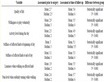
Table 1. System parameters adopted for the mesh convergence analysis.
Table 2. Finite element mesh convergence analysis—Natural frequencies comparison (rpm).
Table 3. Finite element mesh convergence analysis—Natural frequencies relative error.

Figure 3. Figure 3. Relative error between the predicted natural frequencies and [32].
Table 4. Table 4. System parameters for stability analysis.

Figure 4. Natural frequencies versus bearings damping coefficients, for the 1st, 2nd and 3rd vibration modes.

Figure 5. Natural frequencies versus bearings damping coefficients, for the 4th and 5th vibration modes.
are represented by EV158, EV159, EV160, EV161 and EV162, which represent the 158th, 159th, 160th, 161st and 162nd system eigenvalues, respectively.
The numerical procedure using state variable form produces many eigenvalues, which are separated and organized. For this example, using a mesh with 80 beam elements, after filtering and organizing the eigenvalues, it can be observed that the 160th, 161st and 162nd eigenvalues represent, respectively, the 3rd, 2nd and 1st vibration modes of the rotor-bearing system (Figure 4). As the damping coefficient increases, the order of eigenvalues corresponding to the modeshapes may change, as shown in Figure 5. The comparative results depicted on Figures 4 and 5 show that the finite element procedure renders results in good agreement with those presented by [32] , with a maximum 2% relative error.
This analysis shows the influence of the bearing damping on the natural frequencies of the rotor-bearing system. If the bearing parameters chanJge, the damping may vary, changing the vibration behaviour of the entire system. The stability can also be studied based on the eigenvalues. The computation of the damping exponent associated with part “a” of the complex eigenvalues (Equation (11)), renders results very similar to those obtained by [32] , whose results are omitted here for brevity. An analysis of the real part of the complex eigenvalues is carried out for another system and presented in example 2.
3.2. Example 2
This second example consists of a rotor-bearing system composed of a shaft supported by two hydrodynamic journal bearings, similar to that shown in Figure 1. More details can be seen in [6] . The parameters of the system are shown in Table 5.
The exponents associated with part “a” (Equation (11)) of the complex eigenvalues are computed for the rotating system with some sets of parameters associated with the hydrodynamic journal bearings. This analysis is performed to show the importance of the bearing effective damping 2ωCxx/Kxy on the stabilization of the rotating system [2] . The shaft rotating speed is represented by ω, while Cxx is the bearing direct damping coefficient and Kxy is the bearing cross-coupled stiffness coefficient.
For this example, three sets of rotating speeds have been selected (750 rpm, 3200 rpm and 5600 rpm), as shown in Table 6, in order to show how the bearing effective damping and the value of “a” are related to the system stability. The bearing stiffness coefficients remain constant, while the damping coefficients are adjusted
Table 5. System parameters for example 2.
Table 6. Numerical results for example 2 and stability parameters.
for each rotating speed. For simplicity, the cross-coupled damping coefficients are neglected in this analysis.
The results obtained from this stability analysis show that an increase on the direct damping coefficient can stabilize a rotor operating unstably. A sign change on the eigenvalue exponent “a” indicates that the rotor is moving from unstable to stable conditions or vice-versa. The stability analysis based on the real part “a” of the complex eigenvalues associated with the rotor shown in Table 5 provides the same results as those based on the time integration of the rotor governing equation, presented by [6] . It is clear from this analysis that the bearing effective damping 2ωCxx/Kxy is a very important parameter for rotors operating on hydrodynamic bearings. When the effective damping decreases and approaches 0, the system tends to be unstable, and when it increases, the system tends to be stable. On Table 6, a system is considered unstable when a > 0, and stable when a ≤ 0. The values shown on the second and third columns labelled [Km] and [Cm] are the bearing dynamic force coefficients.
The journal dynamic coefficients play a crucial role on the stability of the system, as shown in this second example. By changing the damping coefficients, a stable condition can be established, as shown on Table 6.
4. Conclusions
The appropriate selection of a rotor supporting system is a fundamental step on the design and commissioning of industrial rotating machines. Dynamic force coefficients play a crucial role in the rotor capability to bear undesirable vibrations and to run under stable conditions. The results presented in this work show clearly the importance of selecting the appropriate bearing configuration able to provide enough effective damping to bound the growth of the vibration response at critical operating conditions.
The finite element procedure has been implemented to analyze the stability of high speed turbomachines supported by hydrodynamic journal bearings. The numerical results presented in this work show that the computational procedure implemented for the eigenvalue analysis of damped gyroscopic systems is able to render reliable results, which are in good agreement with the results presented in the technical literature.
The finite element procedure can also be employed to evaluate design and operating changes in high-speed turbomachinery, in order to improve their dynamic response. From the parameters of the rotor-bearing system, its dynamic behaviour can be studied and modified, for example, to avoid its operation near a critical speed, or to guarantee safe operation when traversing critical speeds.