1. Introduction
The purpose of the electrical power system is to deliver good quality, safe and reliable power to the consumers, load centers, industrial plants, etc. The quality and security of power system are disturbed due to the system faults and failures occurring. Faults usually occur due to the lightening flash over, insulation failure, physical damage, short circuit to ground or short circuit in live conductors [1]. A short circuit fault is the most common fault in power systems. A short circuit fault carries huge amount of the current other than the normal operating current. The excessive amount of the current flowing through a circuit can generate tremendous heat which poses risks of fire, damage to the other equipments and potential electrical shocks to the people. If a short circuit is not removed or a faulty portion is not quickly isolated from the healthy system, it will spread into healthy part of the network and may cause over loads and possibly the damage to the transmission lines/cables, bus bars and other equipments. It is therefore, necessary to protect the power system against the short circuits by using short circuit protection devices and ensuring their proper coordination in order to avoid false tripping.
A test distribution network set up by CIGRE comprising WTG, PV solar generation units and sensitive equipment such as VSCs at different locations has been chosen for the study. The single line diagram of this distribution system modeled in DIgSILENT power factory software 15.0 together with appropriate protection devices is shown in Figure 1.
In this network, there are two PV solar generation units of 3 kW and 4 kW connected at bus RC and RD respectively. There is one fixed-pitch fixed speed wind

Figure 1. The single line diagram of CIGRE network modeled in DIgSILENT power factory [2].
turbine generator of 5.5 kW connected at bus R19. The WTG is operated close to unity power factor by using a shunt capacitor. There are two batteries connected at bus RA and at bus RB. These Distributed Generating (DG) units are integrated into the grid by using 0.4 MVA, 20 kV/0.4 kV DyN transformer. The neutral of the transformer is grounded with low impedance, (i.e.
 . Unbalanced loads are aggregated at the 0.4 kV voltage levels and are connected at bus RC, RD, RE, R11 and bus R17. The detailed data concerning different cables/lines used in the network are given in Table 1 in the appendix.
STATCOM controllers for both the PV systems have been developed in order to control oscillations in the DC link and AC voltages by injecting or absorbing the desired amount of the active and reactive powers [3]. The controllers for the Battery Energy Storage Systems (BESS) are developed and are able to control the flow of active and reactive powers through the lines [3]. These controllers also charge/discharge the batteries at different charging rates [3].
The different components of the CIGRE network (i.e. transformer, WTG, lines, bus bars, battery inverters and PV inverters) can be protected either by circuit breakers or by fuses. Typically, transformers below 1000 kVA are protected by using fuses [4]. According to Schneider electric [5] and Danfoss, Low voltage inverters for PV applications and battery storage are protected against short circuit currents by using fuses. Therefore, this study about the protection of LV CIGRE distribution network against short circuit current is mainly performed by using fuses as protection devices. The under voltage relays are used to clear a fault if fuses are unable to clear faults in some conditions. These relays are also used in the case when fuses take longer time to clear fault, such as fault with some fault impedance. The disconnection of the PV solar panels is made by using switch disconnection devices in this study.
The ratings of fuses selected to protect different components of CIGRE network are labeled in Figure 1 and are presented in Table 2 in the appendix. Fuses are selected to allow passage of normal current plus a marginal percentage (i.e. 25%) to allow excessive current only for short duration [5-7].
Some of fuses selected in Table 2 of the appendix are even little less than 125% of the rated current because the next available fuse is of bigger rating. For example, fuse selected for the load-RE is 40 A, whereas 125% of the rated current in the phase C of this load is 43.4 A which is higher than the fuse rating. A 40 A fuse is selected because next available fuse is 50 A, therefore, if 50 A fuse is selected for this load, then it might cause delay in the protection. The selected rating of fuses denoted by ‘*’ shown in the Table 2 is different because of coordination purposes.
The paper is organized as follows: Section 2 presents the simulation results when protection is made against 3-phase faults with and without fault impedance. The over speed protection of the WTG in the case of grid loss due to 3-phase fault is also described in this section. The protection of the CIGRE inverters is presented in section 3. The disconnection of the solar PV cell structure in the case when in island is also described in this section. Section 4 presents the results about the protection against single-phase to ground fault and the disconnection of the WTG in that case. The protection of the CIGRE network in its central part is presented in section 5. Finally, the conclusion about the paper is presented in section 6.
2. The Protection of the Network against 3-Phase Faults
The study about the protection of the network in this case is carried out by introducing a 3-phase fault with and without fault impedance at the different locations of the CIGRE network. The fuses and under voltage relays available at the different locations are used to clear this kind of fault.
2.1. Protection of the Network in Case of 3-Phase Fault without Fault Impedance
For the first case a three phase fault with fault impedance of zero ohm ( = 0) is applied at time equal to t = 5 s at the terminals of the WTG (i.e. bus R19). This kind of fault must be isolated from the grid side and from the WTG side in order to ensure reliability and security in the other parts of the network. The procedure of clearing the fault from both the sides of the applied fault is described below:
The voltage at the WTG bus (i.e. bus R19) due to this kind of fault becomes zero and hence, the active power output of generator becomes zero. According to the technical regulations 3.2.1 for electricity generation facilities with a rated current of 16 A per phase or lower, a WTG must be disconnected if its terminal voltage falls below 0.9 p.u.
When a short circuit appears at the terminals of an induction machine which is operating as WTG in this network, the current produced by WTG starts to increase to a very high value before decaying completely to zero as shown in Figure 2. The rise in this current at t = 5 s is because of inrush current flowing to the faulted point. The induction machines deliver about six times rated current during this time [8-10]. This fault characteristic is due to the inertia in the presence of field flux produced by the induction from the stator. This flux decays on the loss of voltage because of the fault at the terminals of the machine. This current decays to zero as shown in Figure 2 and is because of the loss of field excitation (i.e. loss of stator flux).
The current shown in Figure 2 decays to zero before reaching to the activation time of fuse F9 (i.e. 273 ms at this value of current as seen in Figure A in appendix). The observed current is not within the range of the selected fuse operating characteristics; therefore, the isolation of the WTG from the faulted point is not possible by using the fuse in this case.
An under voltage relay is then used. The voltage is sensed by relay R1 shown in Figure 1 and sends trip signals to the circuit breaker which disconnects the WTG from the faulted point. The time of operation of this relay depends on how low the voltage is at the terminal of the WTG. According to ANSI CS84.1-1995 if the voltage is below 0.5 p.u then the time to clear a fault should be below 0.16 s and if the voltage is in between 0.5 p.u and 0.88 p.u the time to clear fault should be less than 2 s. Since the voltage on the terminals of the WTG due to the fault is zero (i.e. voltage is below 0.5 p.u); therefore, the fault should be cleared within 0.16 s. The operation of the circuit breaker receiving the trip signal by relay R1 is shown in Figure 3. The Breaker status is closed when it shows 1 on the plot and is opened when it displays 0 on the plot as shown in Figure 3.
It can also be seen in Figure 1 that a capacitor bank is used at bus R19 in order to improve the power factor of the WTG; this capacitor also needs protection against the fault at bus R19. The voltage of this capacitor decreases to zero due to the short circuit fault appeared on its point of the connection as shown in Figure 4. The production of the reactive current by the capacitor bank which is required to magnetize the stator winding of the WTG decreases to zero because of its zero voltage at this time t = 5 s. This current is shown in Figure 5.
It can be seen in Figure 5 that the capacitor bank delivers some amount of the reactive current (Minus sign
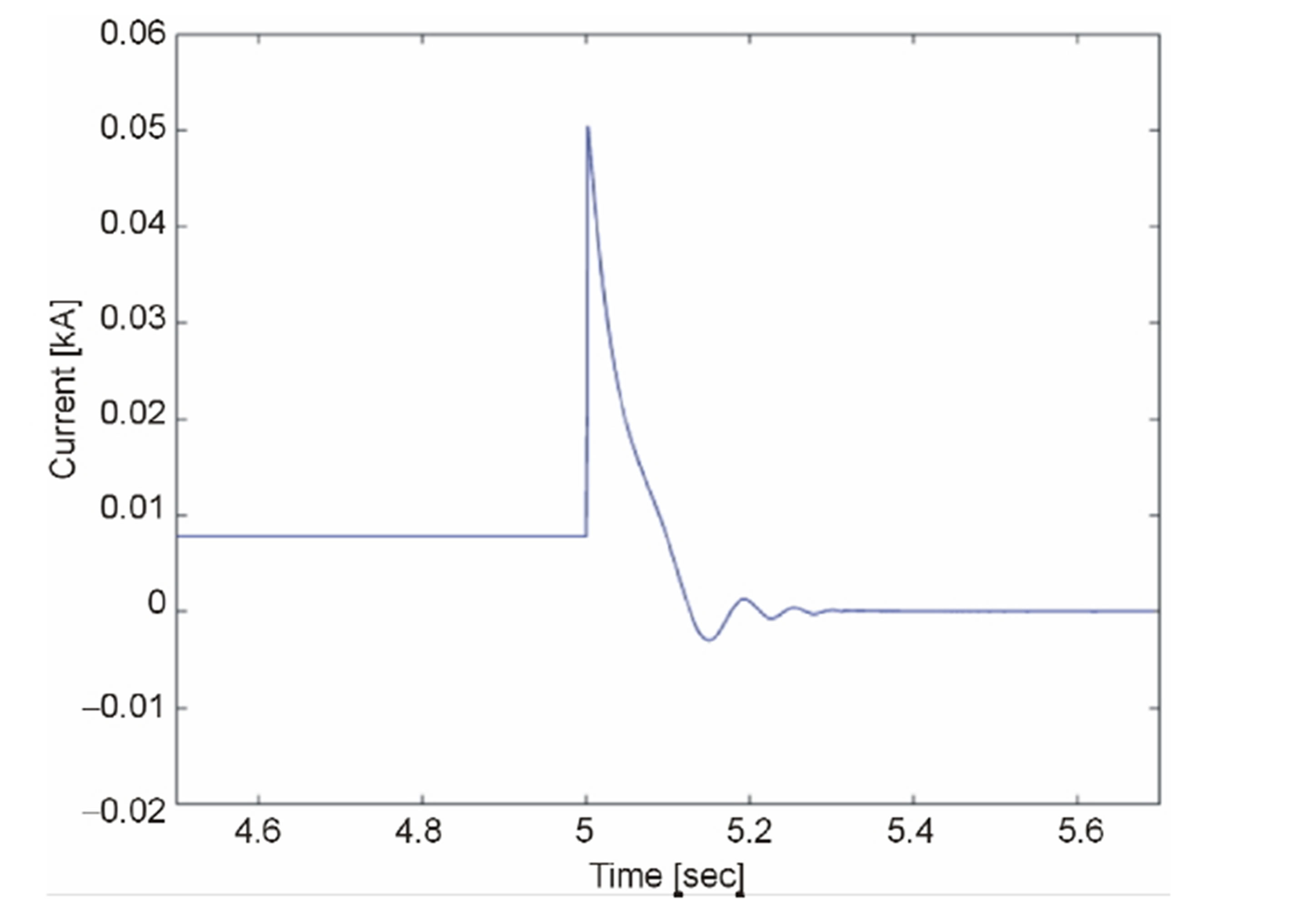
Figure 2. Current of the WTG when fault on its terminals.
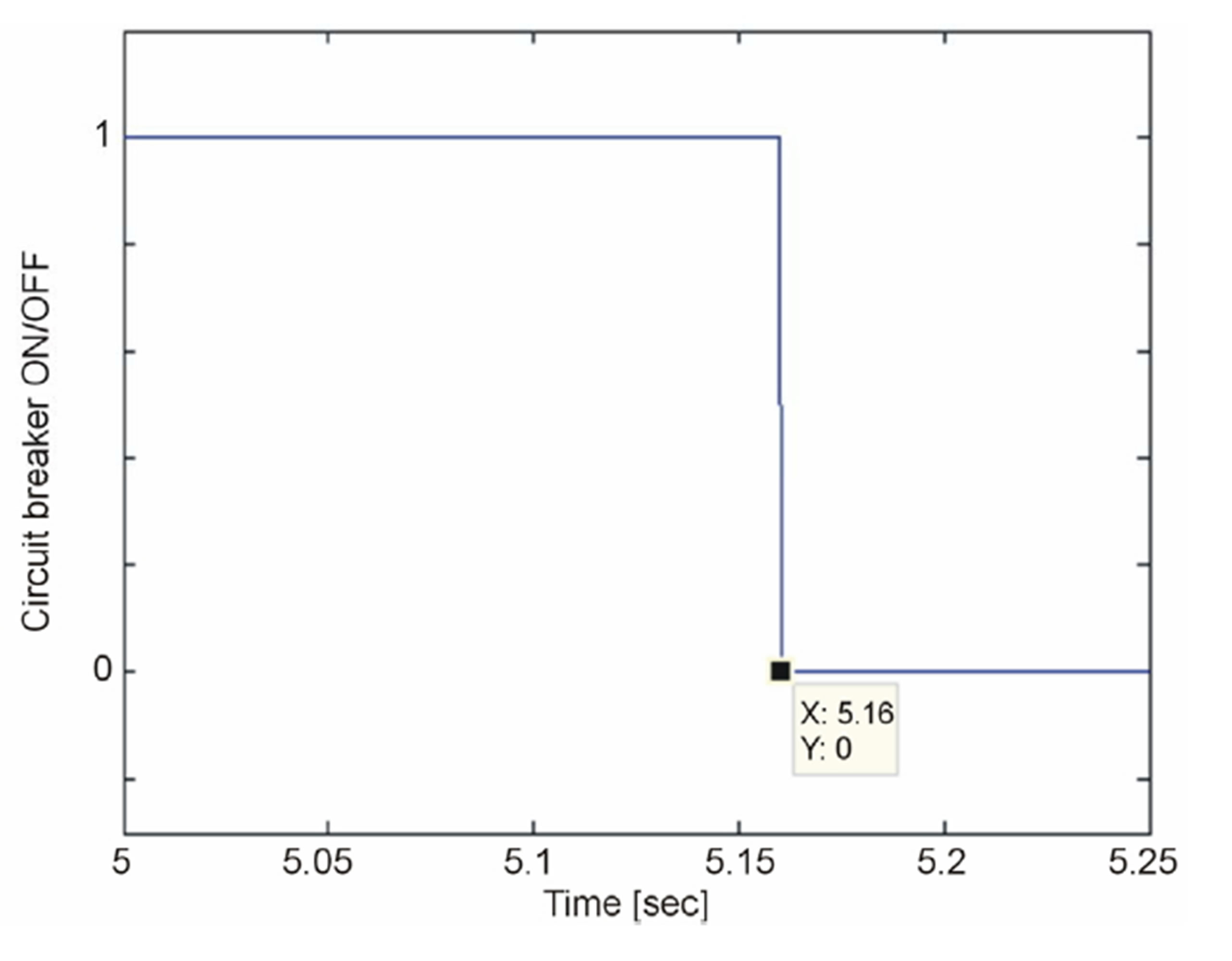
Figure 3. The circuit breaker operation.
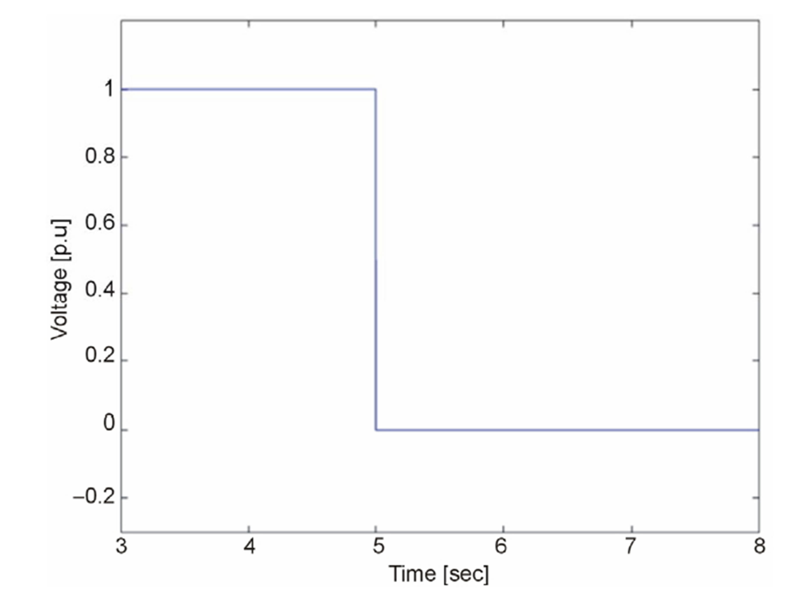
Figure 4. The voltage of the capacitor bank.
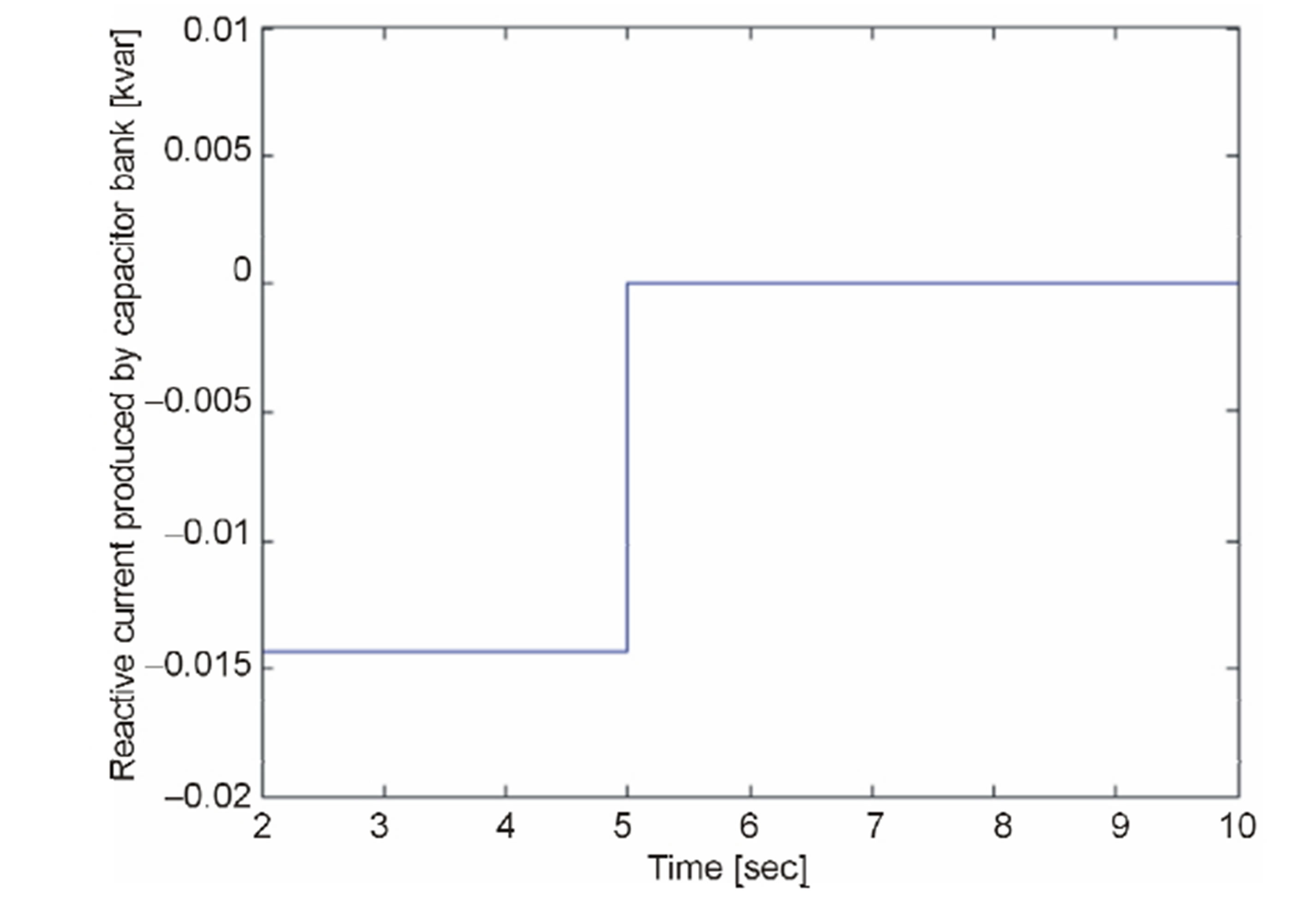
Figure 5. Reactive current delivered by the capacitor bank connected at bus R19.
shows current is injected) in order to excite the stator of the WTG in the normal operating conditions. When the voltage at its terminals becomes zero as shown in Figure 4, its current injection also becomes zero as shown in Figure 5; therefore, the current based protection is not valid in order to protect this capacitor. The under voltage relay R2 shown in Figure 1 is used in this regard. The operation of the circuit breaker used to disconnect the capacitor bank is same as shown in Figure 3 because both the relays are sensing the same voltage and are connected at the same bus.
As three single phase loads are connected on the bus E which makes the voltage on this bus unbalanced, the short circuit current flowing through the upstream cable RE-R19, which is connected on bus R19 (i.e. faulted bus) will also be unbalanced. The current flowing through the three phases of the cable RE-R19 is shown in Figure 6. In normal operating condition, a current with magnitude of 16.5 A is flowing in the three phases of the cable RE-R19. This current increases to 2.56 kA at the instant of fault at t = 5 s as shown in Figure 6. The short circuit currents in the three phases during the fault are a little bit different because of the voltage unbalance.
Fuse F8 is used to disconnect this faulty section of the network from the grid side blows in 313 ms according to the inverse time current characteristics of this fuse as shown in Figure A in the appendix. It can be seen in Figure 6 that the disconnection in the different phases is made at different times since the current is bit different in all the phases. Hence, the fault has been isolated from both the sides of network (i.e. grid side and WTG side).
A WT receiving a constant wind speed, and with no transfer of electrical power, rapidly increases the speed of the generator. Therefore, it is essential that the wind turbines stop automatically if the generator is disconnected from the electrical grid [11]. The Danish wind turbines are required to be protected either by aerodynamic brakes or mechanical brakes [11]. Aerodynamic braking uses pitch angle mechanism and it is used for
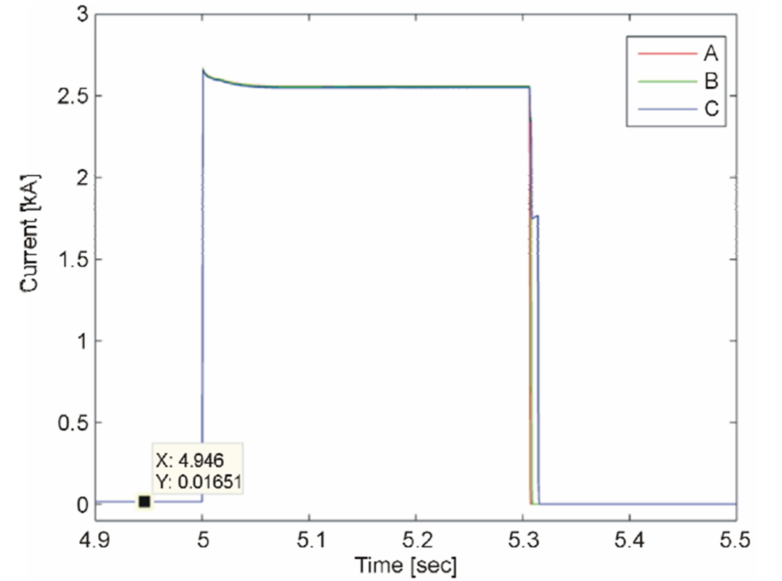
Figure 6. The current flowing through cable RE-R19.
pitch controlled wind turbines or active stall controlled turbines and is expensive for small wind turbines like the ones considered under this study. Mechanical braking is the most common method used for the small wind turbines [12,13] and this mechanism is used to stop the 5.5 kW wind turbine used in the CIGRE network in the case of the loss of the grid supply in this paper.
The block diagram of the mechanical brake model developed in DIgSILENT power factory version 15.0 is shown in Figure 7.
The brake model comprises a switch together with a first order time lag function which is represented by the transfer function 1/1+sT, where T is the time constant that ensures the actuation time of the brake. During normal operating conditions, the generator operates at the speed of 1 p.u and the position of switch remains at 1. However, if the speed of the rotor increases beyond 1.2 p.u [13], the switch changes its position from 1 to 0 and makes the shaft reference speed equal to zero which in turn reduces the mechanical torque of the machine in order to stop the generator. The actuation time (i.e. 10 s) of the brake [14,15] is ensured by setting the time constant (T) of time lag function The braking mechanism is activated at t = 5.6 s as the generator speed observed is more than 1.2 p.u and the brakes are applied on the turbine shaft. The speed of the WTG with braking mechanism is shown in Figure 8. It can be seen in Figure 8 that the WTG has been stopped in the case of grid loss due to 3-phase fault within the actuation time of t = 10 s.
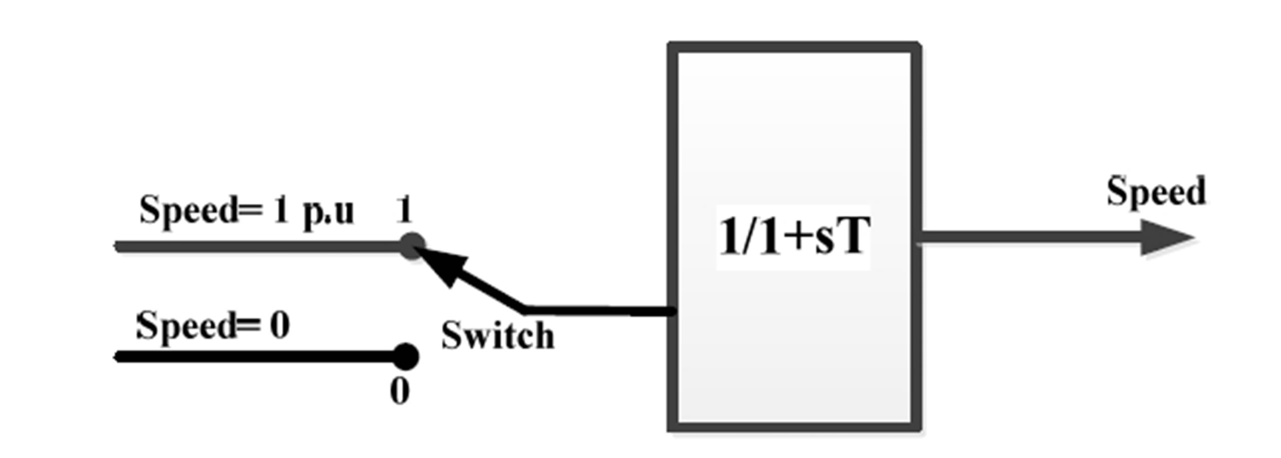
Figure 7. The model of mechanical brake.
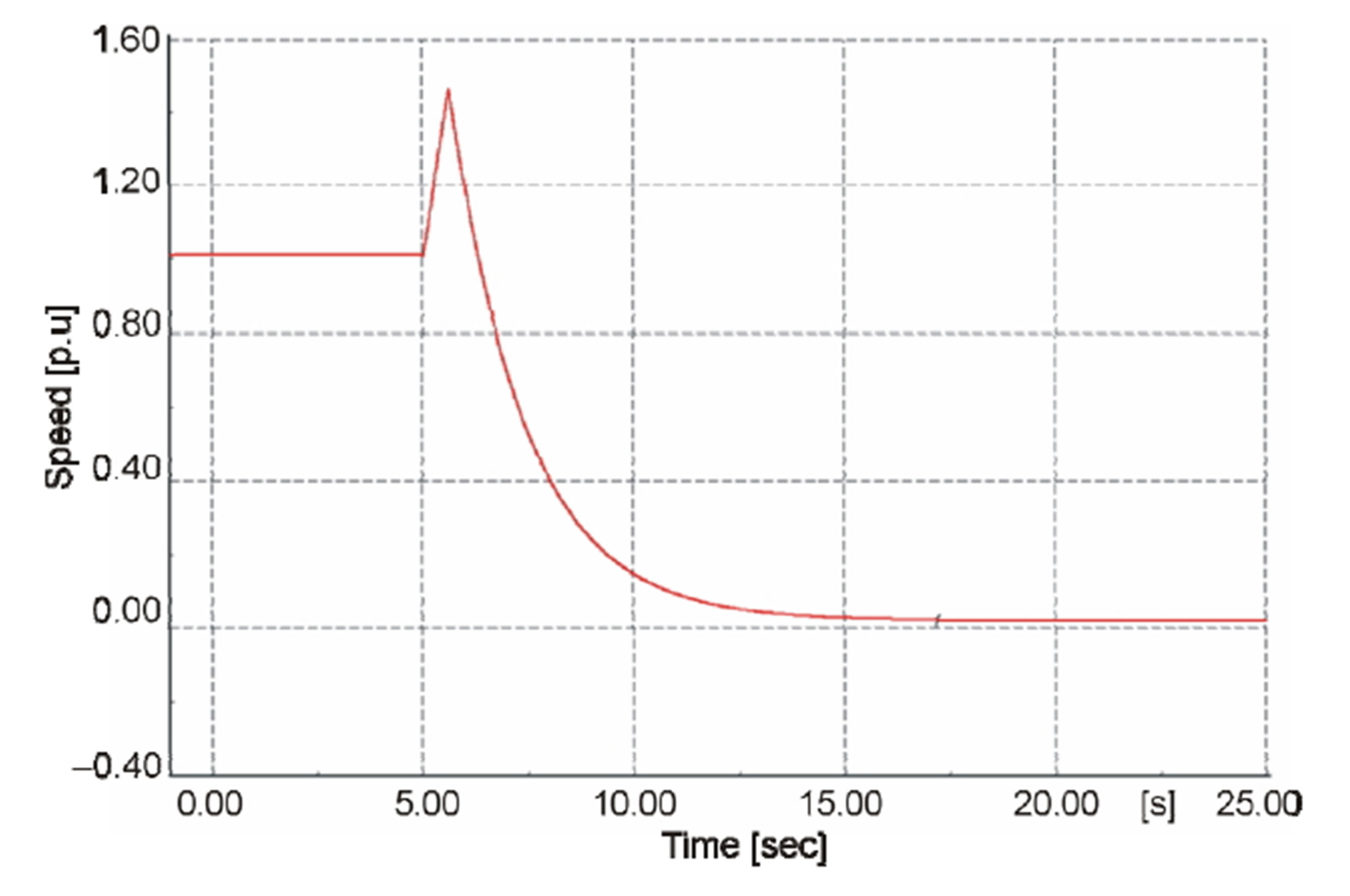
Figure 8. The speed of the WTG with braking mechanism.
2.2. Protection of the Network in Case of 3-Phase Fault with Fault Impedance
A three phase fault with a fault impedance of 0.1 ohms ( = 0.1) is applied on the terminals of WTG (i.e. bus R19) at the time equal to t = 5 s. The short circuit current flowing through the faulted line in the case of fault with fault impedance is small compared to the fault without fault impedance. The inclusion of fault impedance delays the tripping of the over current protection devices. The current flowing through the three phases of the cable RE-R19 in this case is shown in Figure 9.
It can be seen in Figure 9 that the current flowing in the three phases of the cable increases at the instant of the fault at t = 5 s. The currents in the three phases during the fault are a bit different because of the voltage unbalance.
Fuses F6 (backup) and F8 are used to disconnect this faulty section of the network from the grid side. Both fuses have the same rated current; therefore the coordination of these two fuses in made in a way to ensure the disconnection of the portion nearest to the faulted point. The rating of fuse F6 is therefore selected higher than that of fuse F8 as shown in Table 2. By doing this the three single phase loads are not disconnected due to this fault, since the disconnection is made at the point where fuse F8 is used.
It can be seen in Figure 9 that the fuses in the different phases blow at different times since current are slightly different in all phases and hence the faulty section from the grid side is isolated. The voltage on the bus RE and bus R19 is shown in Figure 10 respectively.
It can be seen in Figure 10 that the voltage on both the buses is equal in normal operating conditions and it decreases at the instant of the fault. When the fault is cleared from the grid side; the voltage on bus RE returns
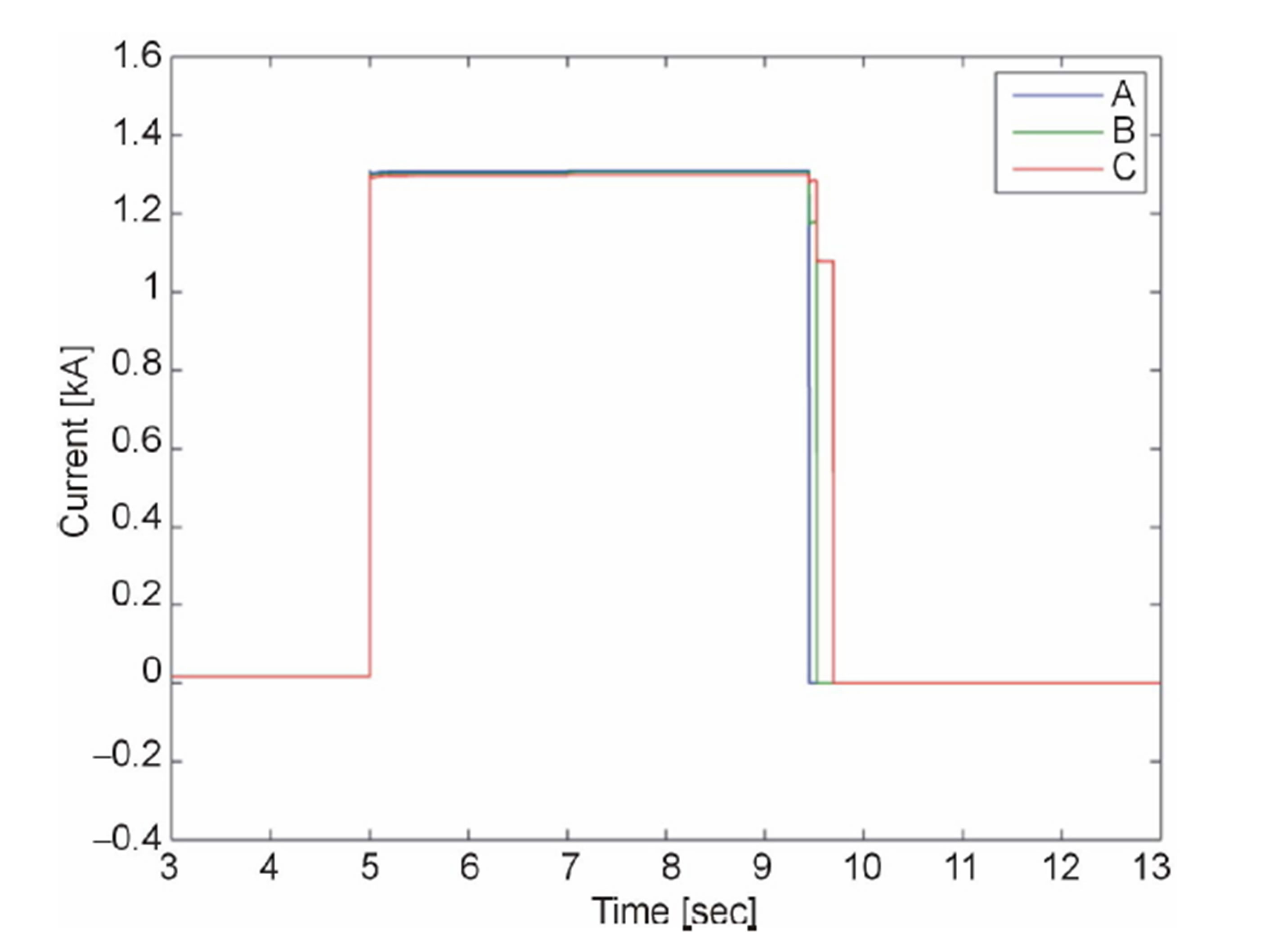
Figure 9. Current flowing through cable RE-R19.
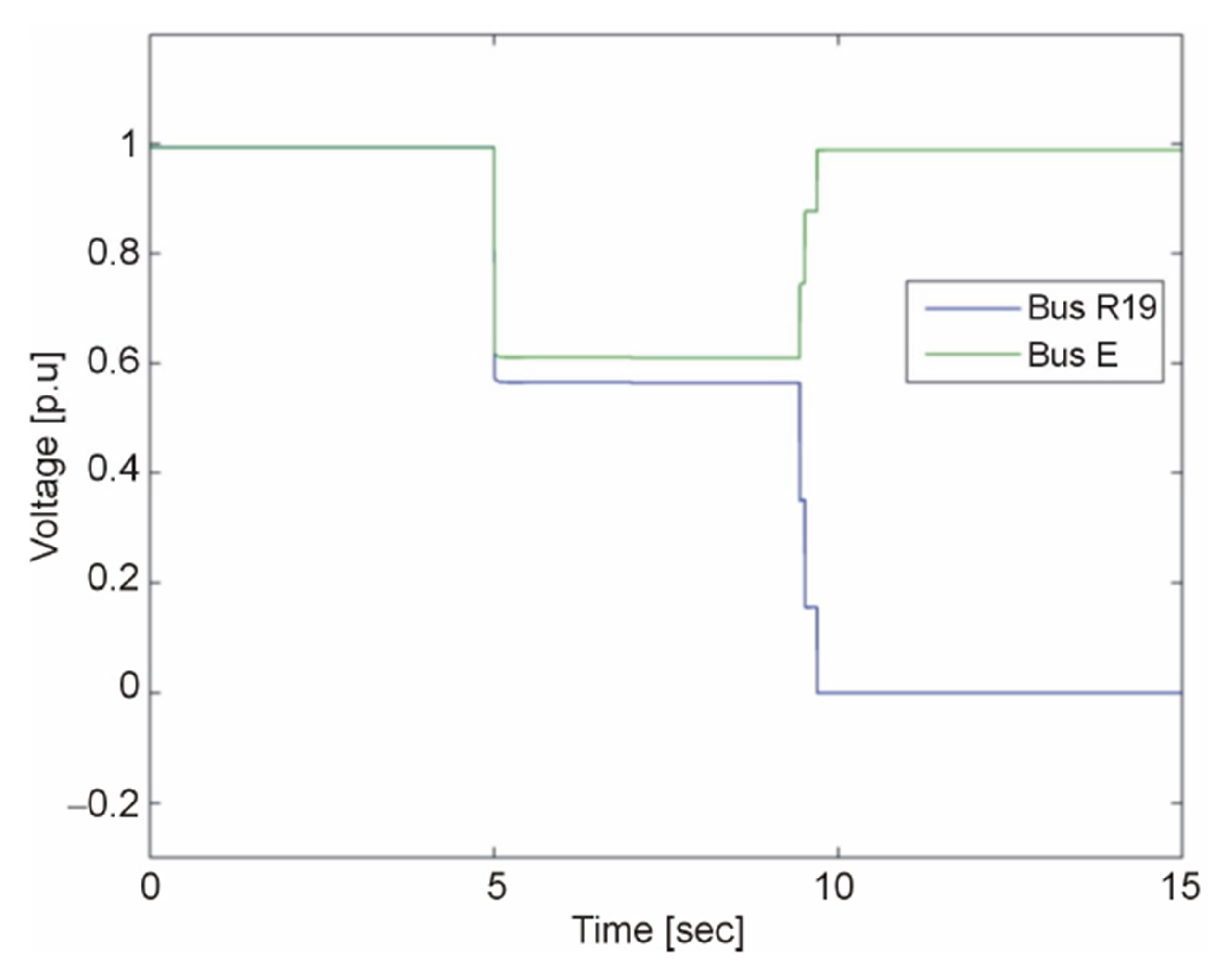
Figure 10. Voltage on bus RE and bus R19.
to the nominal values and the voltage on bus R19 decreases to zero. The switching in these voltages at the time of the fault clearing is due to the opening of the different phases at different times. It can also be seen in Figure 10 that the voltage at the terminal of the WTG is decreased to 0.56 p.u during the fault and it again decreases to zero when grid is isolated from the generator.
Since a fault is only cleared from the grid side and it should also be cleared from the generator side; the disconnection of the WTG can be made either by a current based protection device or a voltage based protection device.
The current delivered by the WTG is shown in Figure 11. It can be seen in this figure. that there is a surge of the current produced by the WTG at the instant of the fault. This current decreases to the value as shown in Figure 11. The reduction in the current shown in Figure 11 is because of the reduction at its terminal voltage. At the time when the grid is disconnected, this current decrease to zero since the WTG has lost grid excitation current. As there is only short time rise in the WTG current and it further decreases during the fault; fuse F9 does not detect this fault and hence the disconnection of the WTG is not possible by using a fuse in this case.
Therefore, an under voltage relay is used in order to disconnect the WTG in this case. The current of the WTG in the case when an under voltage relay has isolated the WTG from the faulted point is shown in Figure 12. Since the voltage on the terminals of the WTG is greater than 0.5 p.u during this fault; then according to ANSI CS84.1-1995 standards the relay R1 sends a trip signal to a circuit breaker which disconnects the WTG from the grid within 2 s.
The speed of the WTG in case of the loss of grid increases beyond the acceptable limits. The mechanical brakes are applied in order to stop the generator as is done in the previous case.
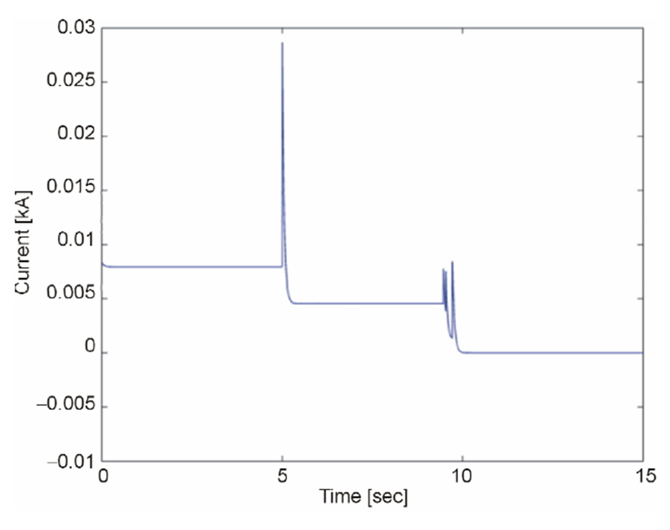
Figure 11. Current delivered by WTG in the case when fuse is used as protection device.
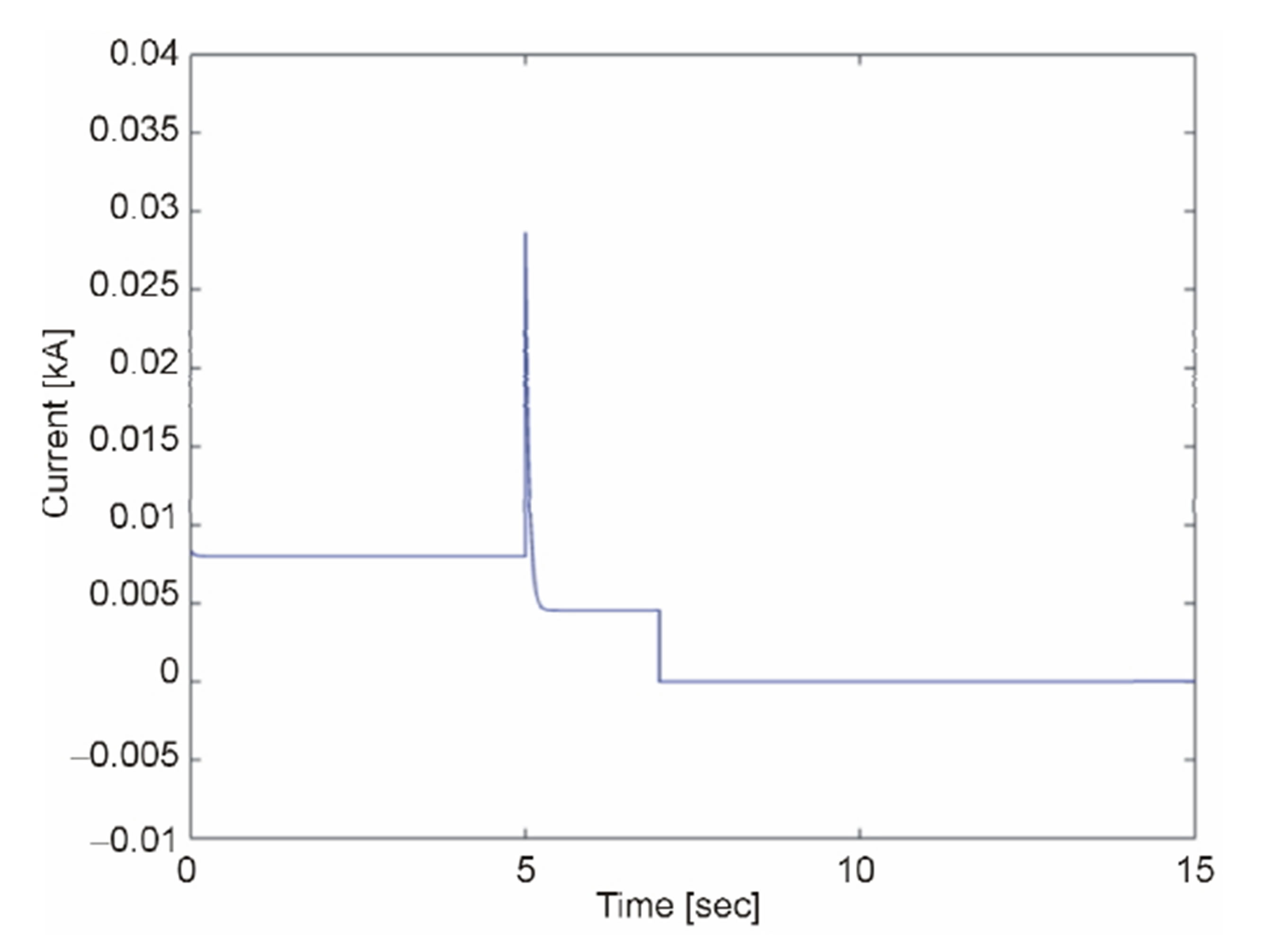
Figure 12. Current delivered by WTG in the case when relay is used as protection device.
To study about the size of the fault impedance where the prescribed protection devices do not detect the fault, various tests have made by applying 3-phase fault at bus R19 using the different values of the fault impedances. The summary about the range of the protection devices at the different values of fault impedances is presented in Table 3 in the appendix.
The voltage at bus RE and bus R19 and the current flowing through cable RE-R19 during the fault at different values of the fault impedances have been presented in this table. The time of the operation of fuse and an under voltage relay have also been shown and decision is made that up to which size of the fault impedance these protection devices (i.e. fuse and an under voltage relay) can operate. This table describes that the protection devices can only operate in a certain range in the case of the fault impedance up to 0.6 ohms. This table also shows that voltage based protection in general is faster than current based protection in all the cases presented in this table.
Now in the case, if the fault impedance is high as for instance 2 ohms as for an arc, the protection devices shown in Figure 1 obviously will not work in this condition according to Table 3. The procedure about the clearing of such kind of faults is described in [16,17].
3. The Protection of the Inverters Used in the CIGRE Network
To study about the protection of the inverters used for the PV and battery applications in the network; a fault should be applied on one of the lines or the buses in the close vicinity of the inverters. A 3-phase short circuit fault with fault impedance of zero ohm ( = 0) is applied on line R10-RC which is connected to the bus RC where PV1 is connected in this regard. This is the line which is fed through the grid and a PV1 inverter; therefore, there is bidirectional flow of the current towards a short circuit point. There will be a surge of the current flowing from the VSC3 towards a faulted line. The VSCs are very sensitive to over currents. The over currents in VSCs lead to the thermal degradation of the IGBT valves and it may also cause a permanent damage [18-20]. The IGBTs can withstand maximum currents of 2 p.u for 1 ms [21]. It is therefore, necessary to protect the IGBTs of the inverters by using ultra-fast protection devices. The fuse F25 is modeled as an ultra-fast (i.e. I-t characteristics are set in such a way that it blows very quickly) and acts instantly to protect VSC3 when the short circuit fault appears in line R10-RC.
The current of the VSC3 is shown in Figure 13. It can be seen in Figure 13 that fuse F25 is blown when the current flowing through VSC3 increases abruptly during the short circuit. The line R10-RC is protected by using fuse F23. The current flowing through this line is shown in Figure 14.
It can be seen in Figure 13 that fuse F25 quickly isolates the inverter from the grid and fuse F23 disconnects line R10-RC from the healthy portion of the network within 68 m s as shown in Figure 14.
PV inverters operate in a certain range of voltages. If voltage goes beyond limits, it will stop its operation [21]. A three phase short circuit fault on the AC terminals of PV1 inverter causes the voltage to go down to zero and hence there is no transfer of the power from a PV1 towards the grid. The dc-link capacitor charges during this period and when it is fully charged there is no path for the current to flow and the PV operates at no load conditions. Due to this reason the dc-link voltage increases very fast. PV generating units in real applications are normally disconnected from the DC bus in order to protect the insulation of PV cells against over voltages. In such a case, the PV panel presents open circuit voltage
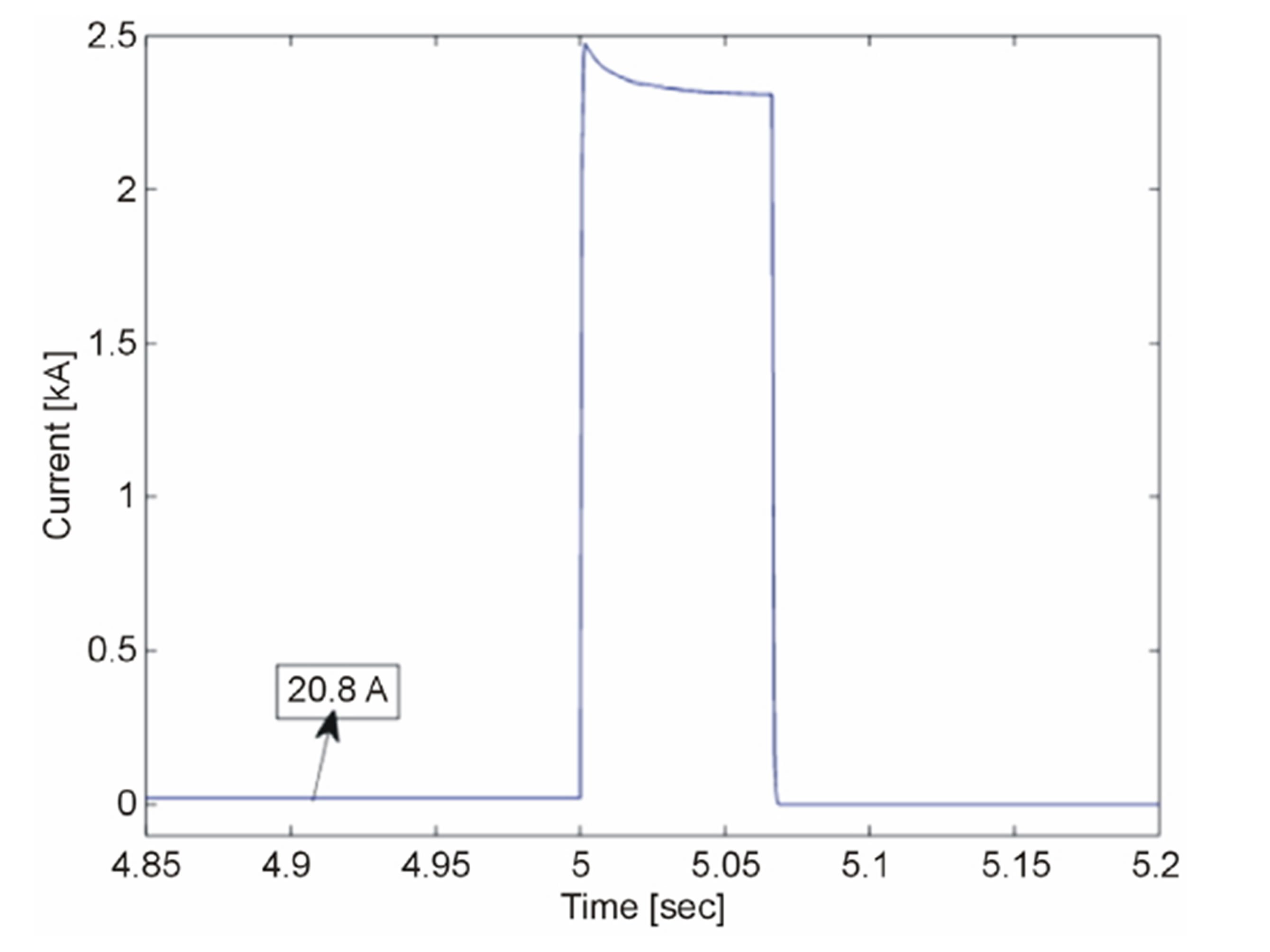
Figure 14. Current flowing through R10-RC line.
(i.e. it is the voltage across the terminals of a PV cell when the current flowing through the external circuit ( ) is zero) at its output with no power generation. The current flowing into the dc-link capacitor is shown in Figure 15.
It can be seen in Figure 15 that there is no flow of the current into dc-link capacitor in the normal operating conditions, since all output power of PV1 is integrated into the grid via VSC3. At the time of grid isolation, dc-link capacitor starts charging through current produced by PV1. Soon after 146 ms, this capacitor is fully charged as shown in Figure 15 and a PV 1 at this time operates at no load and switch-disconnecting device (i.e. D1 as shown in Figure 1) isolates PV1 in this condition. The coordination between fuse F25 and switch disconnecting device D1 is made in such a way that, fuse F25 disconnects VSC3 from the grid due to current surge produced at the time of fault (i.e. t = 5 s) according to its inverse time current characteristics. The disconnection of VSC3 from the grid causes the voltage rise at the DC bus where PV1 cell is connected. Based on the voltage levels, D1 decides the disconnection of PV1 cell from the DC bus. The current produced by PV1 and the voltage at DC bus in normal and at a time of its disconnection is shown in Figure 16.
The protection of other the PV inverter in the grid is also done in the same way by using fuse F13 and disconnection of the PV cell structure is made by D2. The protection of the battery inverters is made by using ultra-fast fuses F17 and F22.
4. Protection of the CIGRE Network against Single Phase to Ground Faults
The majority of faults in the power system are single phase to ground faults [22], and consequently it draws unbalanced currents resulting in unbalanced voltage sags in the network. A single line to ground fault with a fault
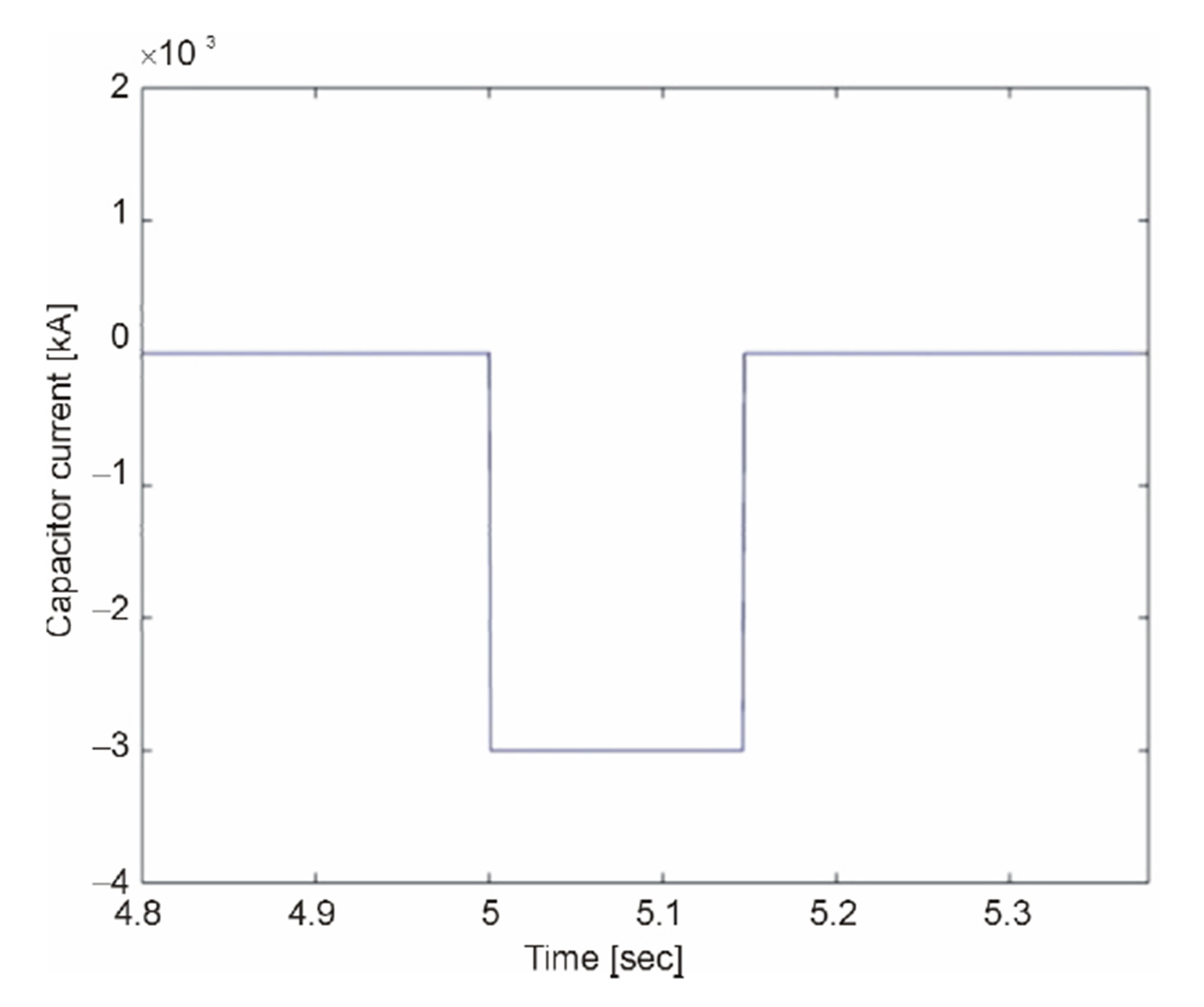
Figure 15. Current of dc-link capacitor.
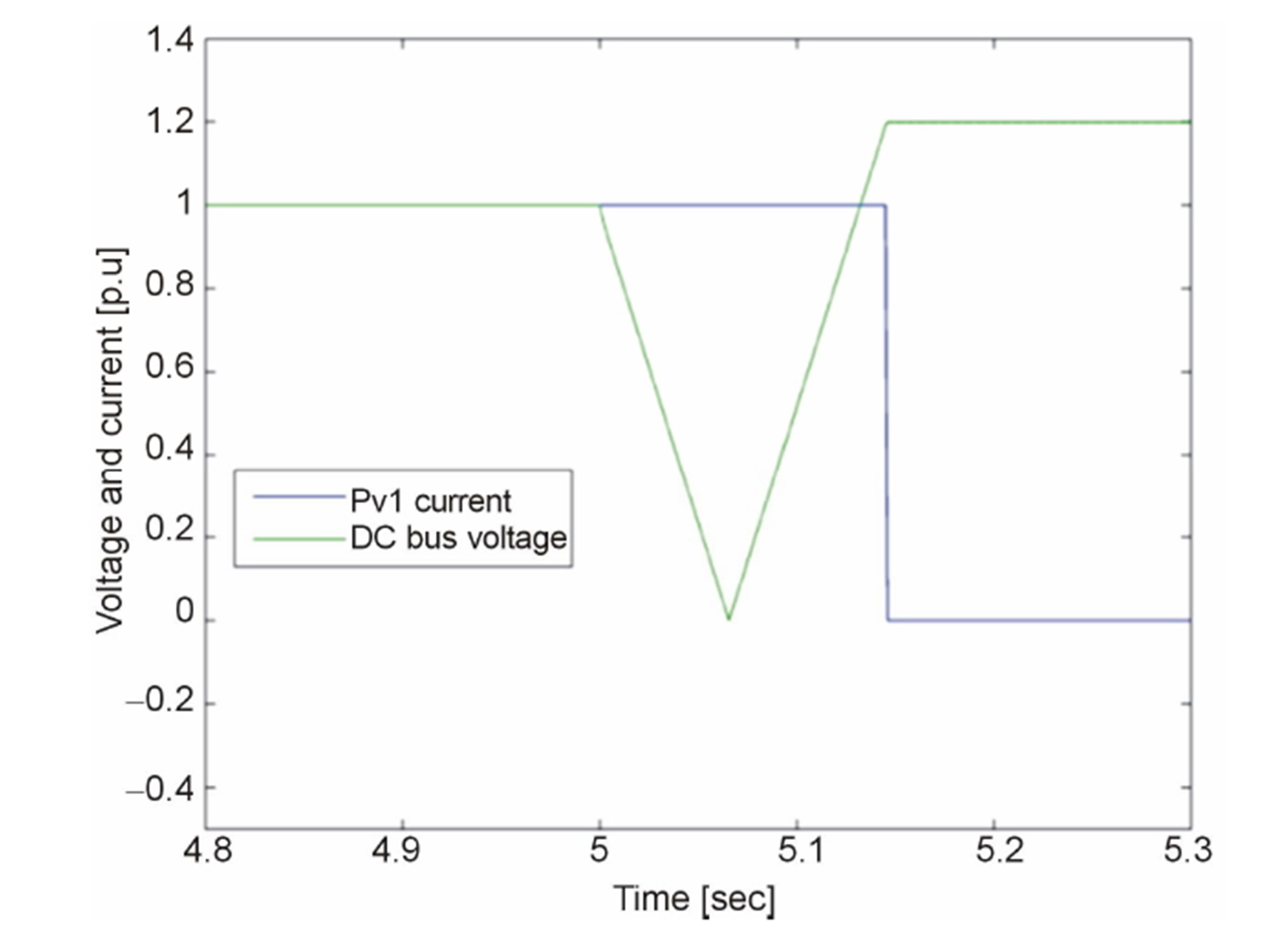
Figure 16. PV1 current and DC bus voltage during normal and island operation.
on phase A having fault impedance of zero ohms is applied at time t = 5 s on line R4-RE in order to observe the performance of the fuses used in the network. The Fuse F6 opens the faulty phase ‘phase A’ from the grid side and fuse F9 opens the same phase from the WTG side. The voltage on bus E due to this kind of the fault is shown in Figure 17.
It can be seen in Figure 17 that the voltage of the affected phase (i.e. phase A) becomes zero when the fault appears on time equal t = 5 s. The voltages in the healthy phases increase during the fault and come back to the steady state value when the fault is cleared. The detailed explanation about the rise of the voltage in the healthy phases during the fault has been presented by the authors in [23].
In case of a WTG connected to unbalanced voltages, the stator currents will be unbalanced. These unbalanced stator currents creates unequal heating in the stator winding which might degrade winding insulation and thereby reducing the life time of the stator winding [24] [25]. The current produced by WTG in its three phases is shown in Figure 18. It can be seen in Figure 18 that there is a huge increase in the current in the phase A of the WTG as this is the faulty phase. The currents in the healthy phases during a fault also increase as shown in Figure 16 and this increase in the current is according to the magnetization current of the stator winding of the WTG.
In order to be on safe side, the WTG should be disconnected in this condition. This disconnection is made by using the under voltage relay R1. As one of the phase is at zero voltage, therefore the relay sends trip signal to a circuit breaker which clears the fault within 160 ms in this case of a fault.
The speed of the generator increases in the case of the disconnection; therefore, mechanical brakes can be applied in order to stop it as mentioned previously.
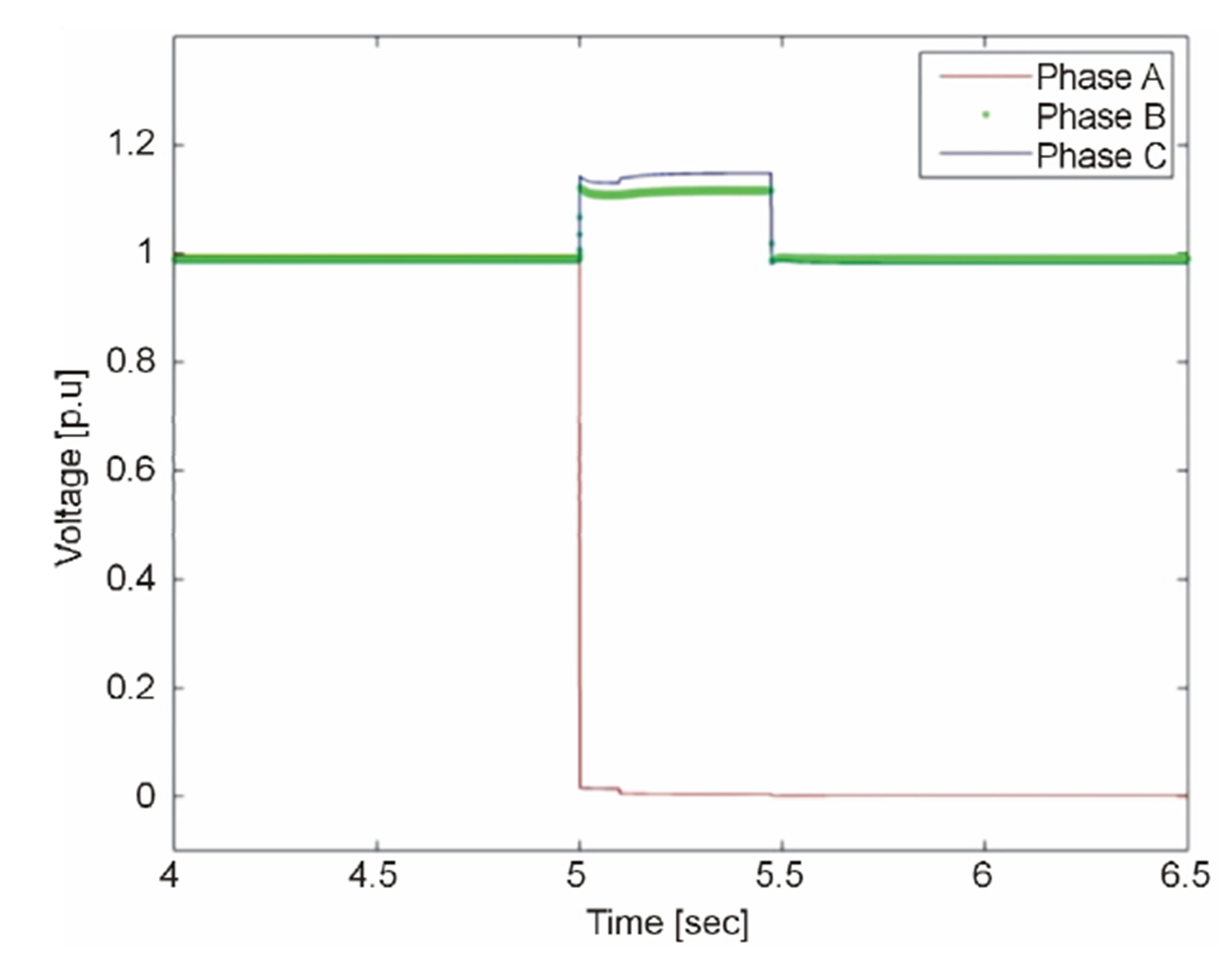
Figure 17. Voltage in three phases on bus RE.
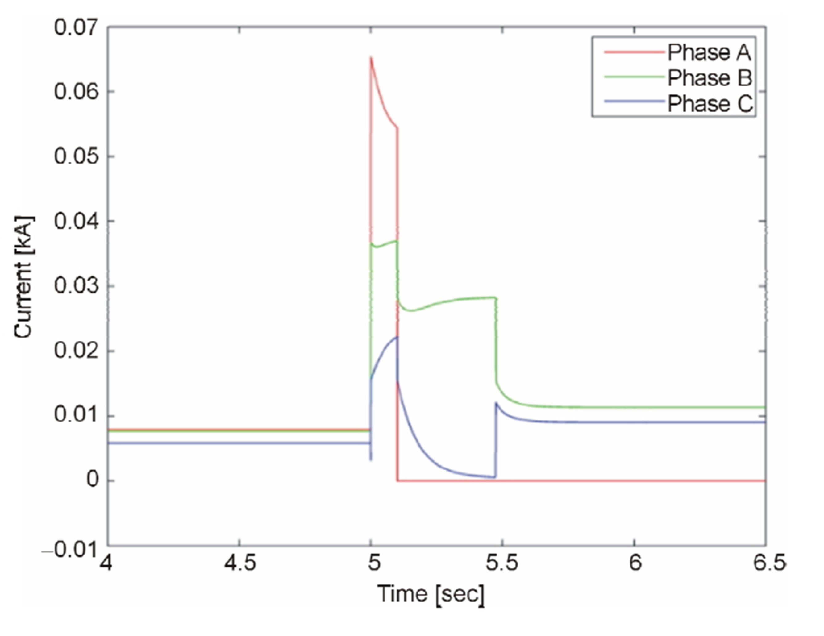
Figure 18. Three phase current of Wind Turbine Generator.
5. Protection of the CIGRE Network in Its Central Parts
The protection of CIGRE in its central part (i.e. from node R1 to R10 in Figure 1) is designed in such a way that it ensures a proper over current protective coordination in a network. The over current protection coordination in the central part of CIGRE network is made by using fuses F15, FA, F14, F10 and F5 as shown in Table 2. Fuse F5 is highest fuse among these fuses due to coordination so if fault occurs nearby the close vicinity of this fuse, it will take longer time to clear the fault. To overcome this problem, the protection in the central part is made by using the under voltage relay.
Again, the fault may occur in the central parts of the network with some fault impedance. The voltage based protection can be a better solution in this regard as well. A 3-phase fault with a fault impedance of 0.1 ohms is applied on the cable R7-R8 of the CIGRE network. The fault appears on the cable at time equal to t = 2 s. The current flowing through this cable is shown in Figure 19. It can be seen in Figure 19 that 1.6 kA current is flowing through the cable during a fault and fuse FA blows within 58 s according to its operating characteristics shown in Figure A in appendix. The fault persist in the network for the long time in this case; therefore, voltage based protection is introduced which clears fault very fast.
The under voltage relay is used at both ends of the cable instead of over current protection devices. These relays (i.e. RL1 and RL2) detect the fault if the voltage on the faulted point decreases below a threshold. The plot of the current flowing from the both ends of the cable (i.e. from the grid side and from the DGs side) when under voltage relays are used at the both ends of the cable is shown in Figures 20 and 21 respectively.

Figure 19. Current flowing through cable R7-R8.
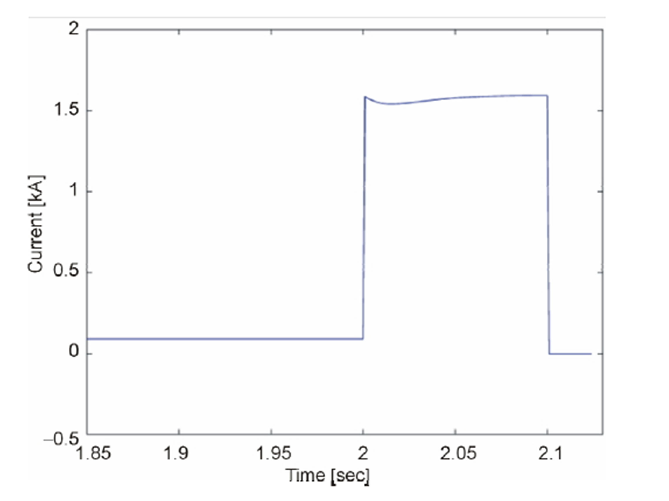
Figure 20. Current flowing through cable R7-R8 from the grid side.
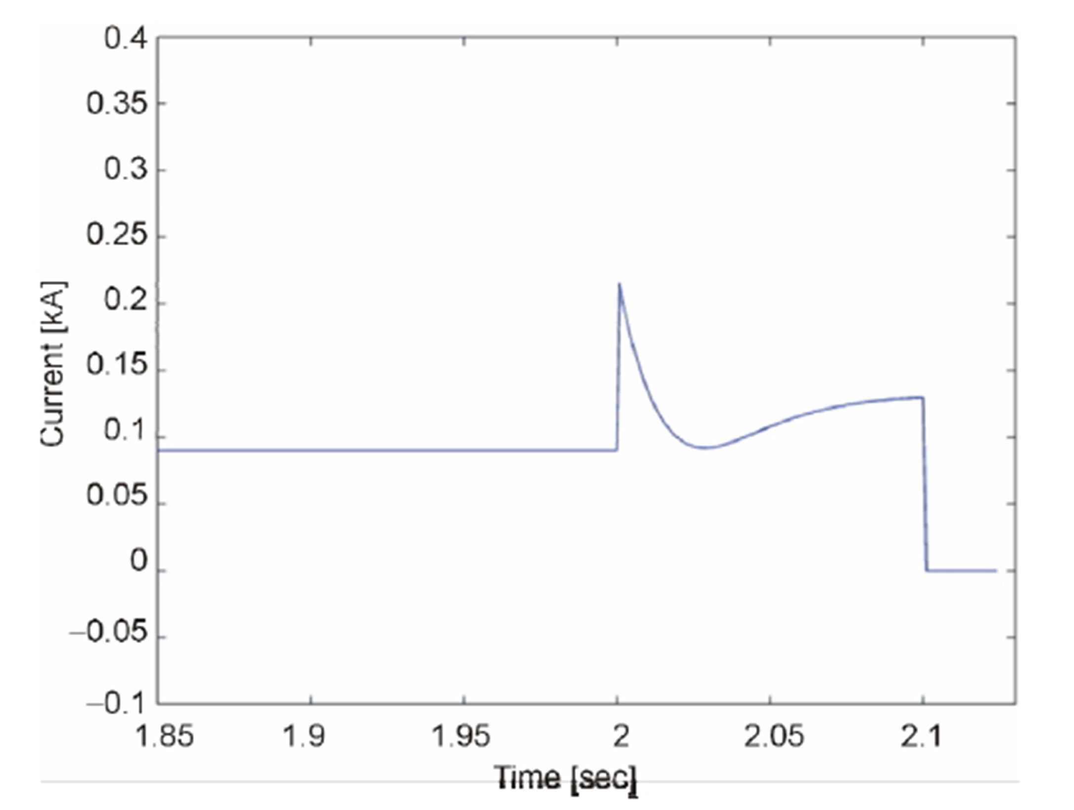
Figure 21. Current flowing through cable R7-R8 from the DGs side.
The under voltage relay used at the grid side end of the cable measures the voltage and sends trip signal to the circuit breaker. It can be seen in Figure 20 that the circuit breaker has disconnected a faulted section from the grid side within 100 ms. Similarly, the under voltage relay used on the DGs side of the cable sends the trip signal to its circuit breaker which clears fault within 100 ms as shown in Figure 21. The over shoot in the current as shown in Figure 21 at the instant of fault is due the current surge produced by the inverter based DG units.
6. Conclusion
The protection against 3-phase fault with and without fault impedance in different portions of the CIGRE network has been proposed. The clearance of the fault in CIGRE network is mainly proposed by using fuses because of economic reasons and if fuses are unable to detect the fault as analyzed for the cases in previous section, the clearance of fault is done by using the under voltage relays. The disconnection of the WTG in case of the symmetrical and unsymmetrical faults is made by using current-based and voltage-based protection devices. The over speed protection in the case of grid loss due to 3-phase and single phase to ground fault by using mechanical brakes is also studied in this paper. The over current protection of the inverters is made by using ultrafast fuses and the disconnection of PV solar cell structure in the case of loss of grid is made by using switch disconnection devices. The protection of the CIGRE network in case of the forward direction of the current (i.e. grid side) is made by using the fuses and the protection in the case of reverse direction of the current (i.e. DG side) due to islanding is made by using the under voltage relays.
7. Acknowledgements
We are thankful to Kai Strunz for providing the CIGRE test network for LV distribution network. I, Ghullam Mustafa am thankful to Quaid-E-Awam University of Engineering Sciences and Technology, Nawabshah, Sindh, Pakistan for the support and funding.
Appendix
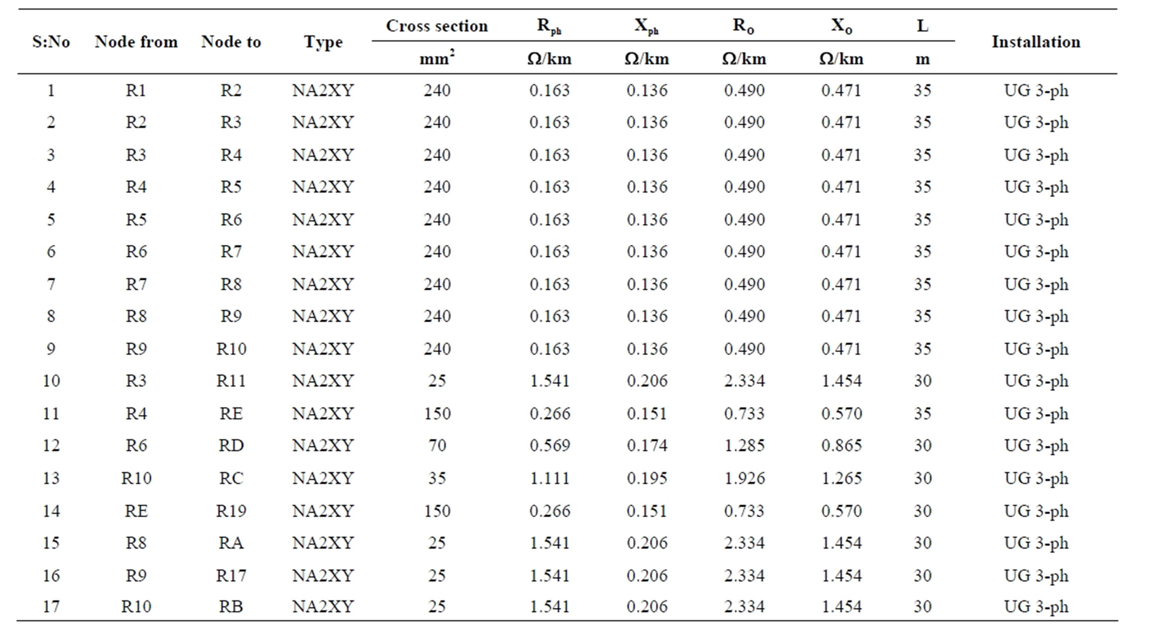
Table 1. The data about the different cables used CIGRE network.
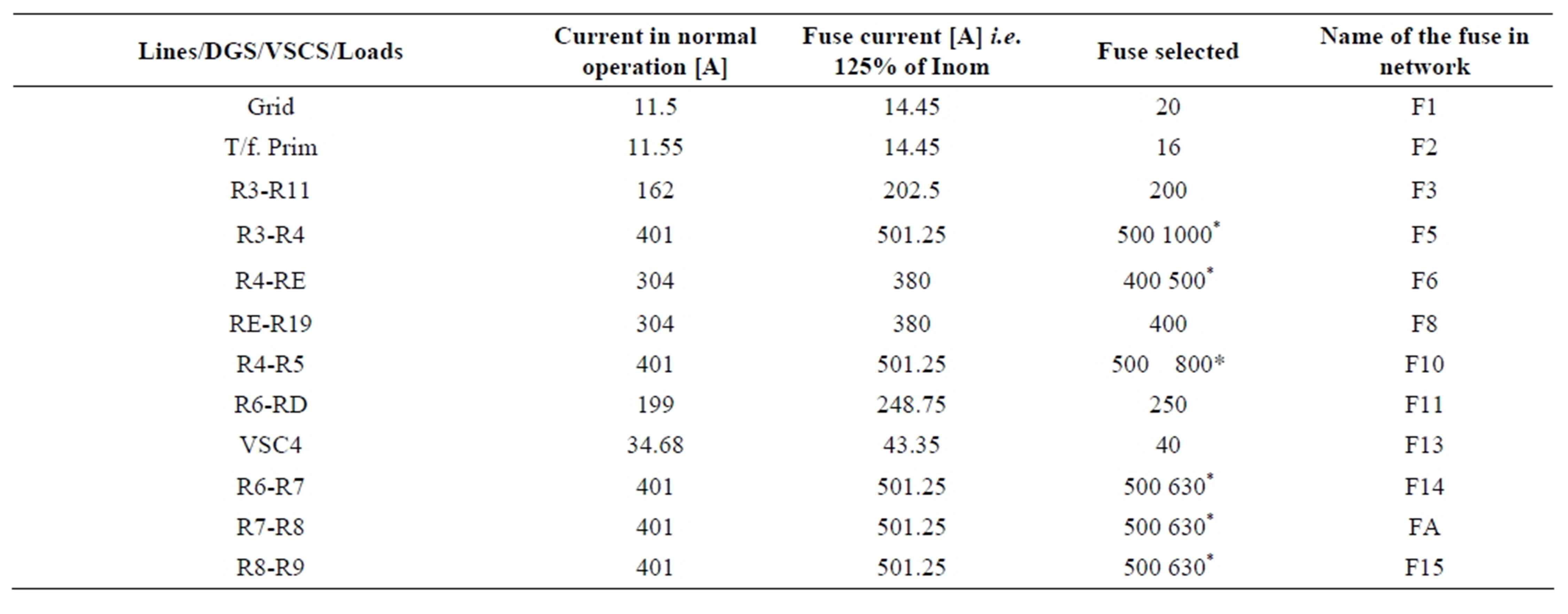
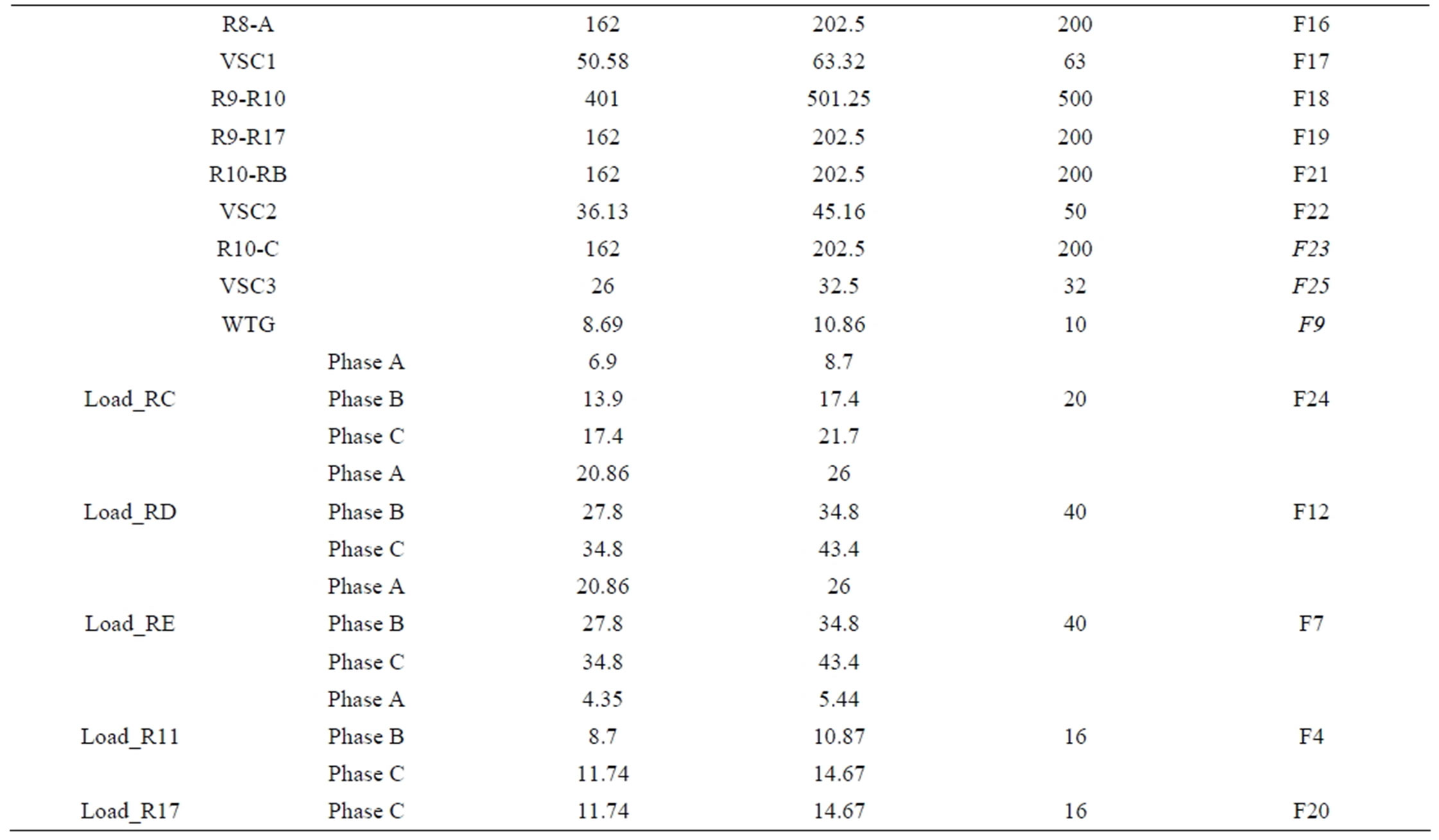
Table 2. The ratings of the different fuses used at different location of the CIGRE network.
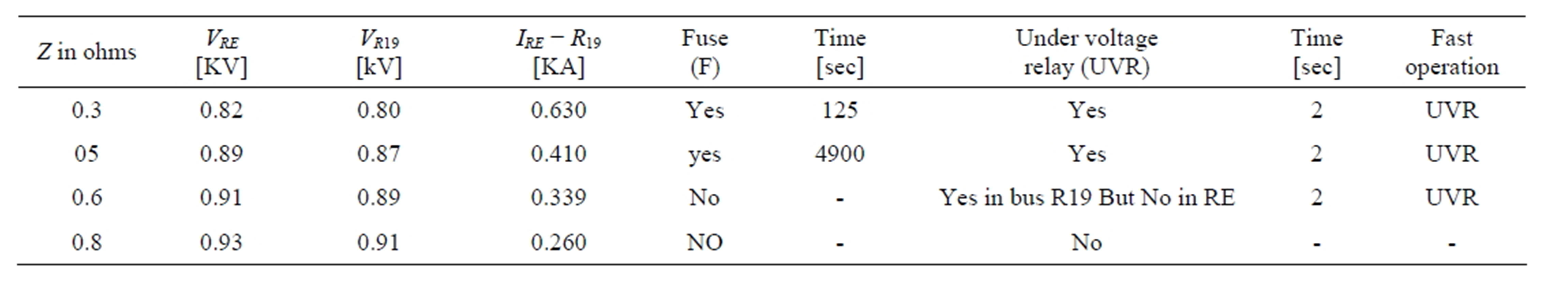
Table 3. The study about the range of the detection of the protection devices with respect to fault impedance.
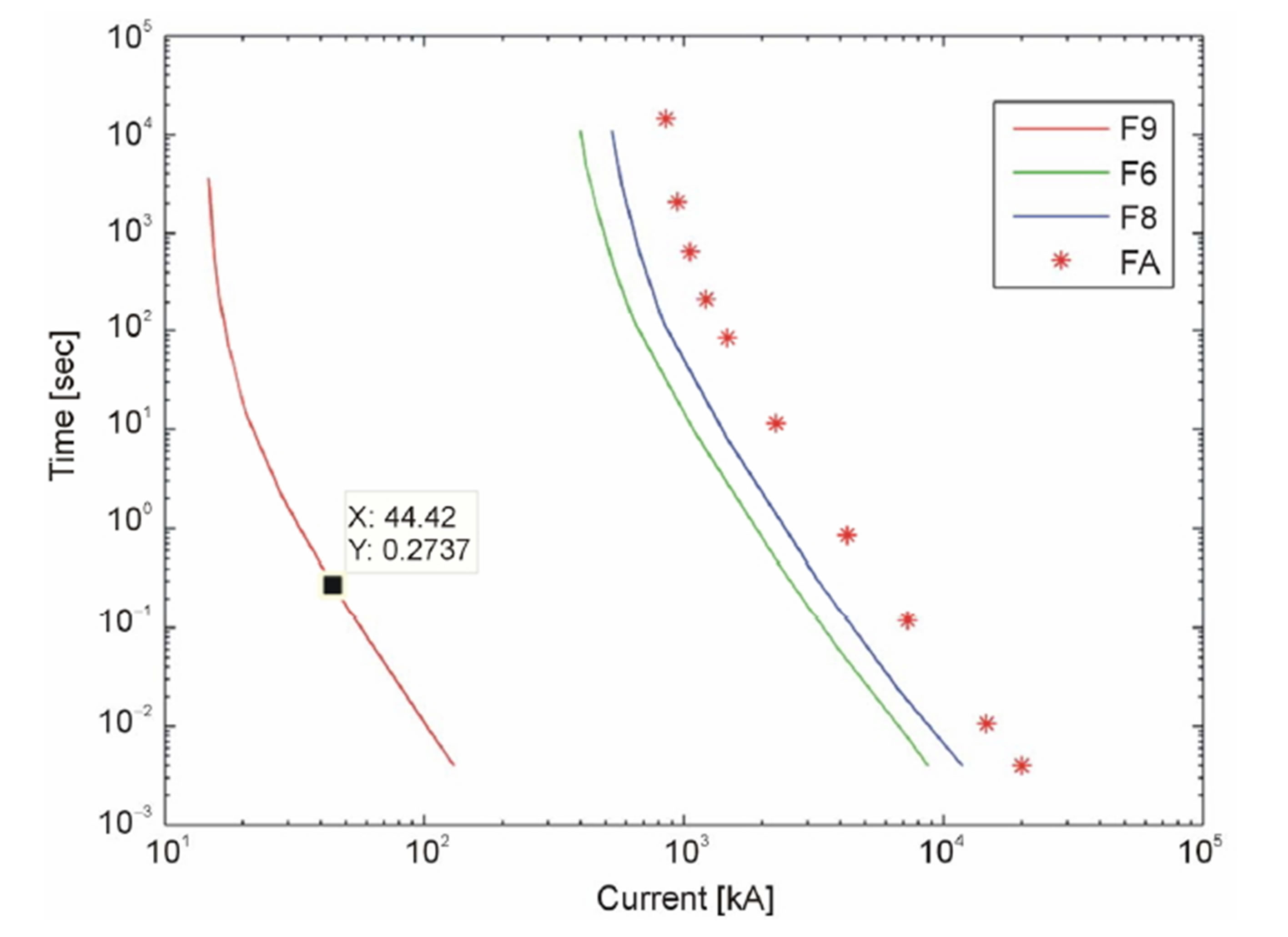
Figure AInverse current characteristics of some of the fuses used in CIGRE network.
NOTES
1) Subject Classification: Smart Grids.
2) All authors are mutually agreed.
3) It’s the original work of all the authors.
4) We did not submit this manuscript before.