On Ultra Extended Cyclic Prefix in Orthogonal Frequency Division Multiplexing (OFDM) Systems: The Case of LTE Downlink ()
1. Introduction
Orthogonal Frequency Division Multiplexing (OFDM) is a multi-carrier scheme used in modern broadband wireless communication systems to transmit data over a number of orthogonal subcarriers. Whereas conventional transmission uses only a single carrier modulated with all the data to be sent, OFDM breaks the data to be sent into small chunks, allocates each sub-data stream to a subcarrier and subsequently sends the data in parallel orthogonal sub-carriers. OFDMA (orthogonal frequency division multiple access) dynamically assigns subset of sub-carriers to individual users using either Time Division Multiple Access (TDMA—i.e., separate time frame) or Frequency Division Multiple Access (FDMA—i.e., separate channels) technique. In the Long-Term Evolution (LTE) systems, two frame types are supported namely: Type 1 (used in Frequency Division Duplexing—FDD) and Type 2 (used in Time Division Duplexing—TDD). OFDMA at the physical layer, in conjunction with a Medium Access Control (MAC) layer, provides optimized resource allocation and quality of service support for different users. The smallest modulation structure in LTE is one symbol in time domain and one subcarrier in frequency domain. The size of various fields in the time domain is expressed as a number of time unit Ts  32.25 nanoseconds. Downlink and uplink transmissions are organized into radio frames with frame duration Tf = 10 ms duration. The time and frequency domains are organized in a grid of physical resource blocks spanning a number of subcarriers and time slots. A Resource Block (RB) is the smallest unit to which user traffic is allocated (i.e. two users cannot share one RB). In the time domain, RB spans one slot of 0.5 ms duration. The number of OFDM symbols in a slot depends on the cyclic prefix length and configured sub-carrier spacing. The slot consists of 7 or 6 consecutive symbols. In the frequency domain, RB spans 180 kHz, consisting of 12 consecutive sub-carriers with sub-carrier spacing of 15 kHz. The total number of sub-carriers during one slot is termed Resource Grid (RG), and the smallest unit, one symbol length on one sub-carrier, is called a Resource Element (RE). In case of multi-antenna transmission, one RG is defined per antenna port. Allocation of RBs to user is done by the scheduler and scheduling decision is taken during each Transmission Time Interval (TTI) of 1 ms for each sub-frame. Ajofoyinbo and Orolu [1] proposed an optimal allocation technique of radio resource in cellular LTE downlink based on truncated dynamic programming under uncertainty. In an earlier work, the authors proposed an optimal allocation methodology of radio resource in cellular LTE downlink based on dynamic programming (Ajofoyinbo and Orolu [2]). A radio frame carries both physical channels and physical signals. When transmitted signals arrive at the receiver by more than one path of different length, the received signals are staggered in time; this is multipath propagation. To mitigate the effect of dispersed channel distortion, Cyclic Prefix (CP) is introduced to eliminate Inter-Symbol Interference (ISI). CP involves copying a section of the end of the main body of an OFDM symbol and appending it to the start of the OFDM symbol. This process does not change the frequency content of the signal as the signal includes the same set of frequency domain component. Guard Interval/Time (GT) is the time spacing between symbols being transmitted to prevent Inter-Symbol Interference (ISI). It is implemented as CP to completely eliminate ISI and to preserve orthogonality among OFDM subcarriers; provided the GT length is sufficiently greater than channel delay spread. OFDM modulation in a transmitter includes Inverse Fast Fourier Transform (IFFT) operation and CP insertion. In OFDM receiver, the CP is removed before the packet data are sent to the Fast Fourier Transform (FFT) operation for demodulation. The FFT/IFFT provides a means of quantifying the set of the frequency domain components included within a time domain signal. The FFT algorithm computes efficiently components of waveform while IFFT algorithm translates the output of FFT back to sampled data. In recent times, researchers have carried out studies in different areas of OFDM systems, especially in relation to mitigating the effect of multipath propagation. In Osman and Rahman [3], a method was proposed to determine the optimal guard time length for mobile WiMAX system over ITU-R M.1225 multipath fading channel. The results show that the optimum values of the GT are approximately dependent on the maximum delay spread. Delay spread values are found to be directly related to the propagation environment and not on the system operating frequency (Nee and Prasad [4]). Delay spread is not constant in wireless mobile communication channel and its values can span from very small value (say, tens of nanoseconds) to large values (say, microseconds) depending on the terrain and distances. Study carried out by Rappaport et al. [5] revealed that urban areas have Root Mean Square (RMS) delay spreads on the order of 2 - 3 microseconds, about 5 - 7 microseconds in open and hilly residential areas, and high rise urban areas exhibit larger delay spreads in excess of 20 microseconds. In their own contribution, Seidel et al. [6] showed that delay spreads are less than 8 microseconds in open in macro-cellular channels, less than 2 microseconds in micro-cellular channels, and 50 - 300 nanoseconds in pico-cellular channels. Moreover, the work of Rappaport [7] revealed that for indoor office building, RMS delay spread is 35 nanoseconds, while at factory buildings the delay spread goes up to 300 nanoseconds. In Tarasak et al. [8], it was shown that with only two transmit antennas, Cyclic Delay Diversity (CDD) effectively improves symbol error rates performance and reduces outage probability significantly especially when channel delay spread is short. Siddiq [9] investigated variable length CP in OFDM using multipath delay tracking and found that the proposed system saves about 47.6% of the time and power spent by the same constant length CP in OFDM system tested under the same conditions. Ghanbarisabagh et al. [10] investigated the problem of cyclic prefix reduction for OFDM system over multipath fading channels, and proposed two Time-domain Equalizer (TEQ) schemes for OFDM systems operating two-path fading channel to cancel the residual effect of ICI and ISI caused by the CP length being shorter than the Channel Impulse Response (CIR). The authors found that the proposed receiver can achieve better Bit Error Rate (BER) performance than the conventional OFDM receiver under two-path fading channel. Li et al. [11] analyzed the effect of cyclic prefix length and subcarrier bandwidth on system interference and capacity. In particular, their work investigated optimal selection of cyclic prefix and sub-carrier for OFDM signal in Mobile Satellite communications channel. Moreover, the authors found that in OFDM based satellite mobile communications, time delay spread of satellite channel is much smaller than that of terrestrial channel, so the CP length can be shortened in order to improve the system performance. Their results also show that setting a large sub-carrier bandwidth and removing CP can restrain the interference. In view of the fact that multipath propagation is dependent upon the surrounding physical environment and the geometric relationships between transmitter and receiver, the delay dispersion appears random. The existing extended CP can only address delay spread of up to 16.67 µs. The aim of the current work is to propose an extension of the extended CP to effectively address delay spread beyond 16.67 µs. This proposed extension is herein called “ultra extended CP”. The remainder of this paper is organized as follows. In Section 2, the problem definition is presented and Section 3 covers problem solution. Simulation and discussion of results are presented in Section 4 and Section 5 concludes the paper.
2. Problem Definition
In the downlink and uplink of UMTS (Universal Mobile Telecommunication System) LTE, transmissions are organized into radio frames that are 10 milliseconds (ms) long in time duration and each radio frame consists of ten sub-frames of 1 ms each. A Resource Block (RB) is one slot in the time domain and twelve consecutive subcarriers in the frequency domain. RB is the smallest unit to which user traffic is allocated and two users cannot share one RB. Scheduling decision is taken during each Transmission Time Interval (TTI) of 1 ms for each sub-frame; which translates to two RBs. Relevant parameters of Type 1 Radio Frame are presented in Figure 1 below.
Time domain fields are typically defined in terms of the basic time unit, Ts (3GPP [12]). That is, the time unit is given as an integer number of Ts.
 (1)
(1)
where  is the FFT size.

One way to prevent ISI is to create a cyclically extended GT where each OFDM symbol is preceded by a periodic extension of the signal itself. The signal is always continuous at the interface between the cyclic prefix and the main body of the OFDM symbol. One fundamental condition for orthogonality between the subcarriers is that each sub-carrier has integer number of cycles in the FFT processing interval. The resultant effect is that all sub-carriers are mutually orthogonal within the FFT interval.
The result of multipath propagation and the mitigating effect of CP are shown in Figure 2. DSmax represents the maximum delay spread.
The duration of the CP should be longer than the duration of the maximum multipath delay spread which can occur in the channel. As presented in Figure 2, the total symbol duration (Ttotal) is given by Equation (2):
 (2)
(2)

Figure 2. Result of multipath propagation and mitigating effect of CP.
where  is the guard interval/time, and T is the useful symbol duration.
LTE specifies both normal and extended CP lengths. The normal CP results in 7 OFDM symbols per slot while the extended CP gives 6 OFDM symbols per slot. Table 1 shows the CP lengths for the downlink of LTE.
In the Base-2 FFT algorithm, 210, 211 and 212 points correspond to 1024, 2048 and 4096 FFT size respectively. The objective of the current work is to investigate the case of an ultra extended CP for 15 kHz subcarriers spacing using 1024 FFT size (i.e., N = 1024 complex samples per OFDM symbol in time domain).
3. Problem Solution
A major parameter associated with the use of OFDM in LTE is the available channel bandwidth as it influences several decisions including the number of sub-carriers in the OFDM signal. The channel bandwidths that are currently supported by LTE are: 1.25 MHz, 2.5 MHz, 5 MHz, 10 MHz, 15 MHz and 20 MHz. The sub-carriers are spaced 15 kHz apart from each other; and to maintain orthogonality among the subcarriers, the symbol duration is defined as the reciprocal of the subcarrier spacing. OFDM symbols have a basic duration of 66.667 µs. This is called the useful symbol duration, which translates to 2048 complex samples per OFDM symbol in the time domain.
3.1. Existing CP Time Durations
As stated in Section 2 above, to provide consistent and exact timing definitions, time intervals within the LTE specifications are defined as multiples of basic unit Ts. Given that the duration for one slot is 0.5 ms (=500 µs), the existing CP time durations are analyzed as follows:
1) The normal CP The time duration for the first CP is obtained as:
 (3)
(3)

Table 1. CP lengths for the downlink of LTE.
The value 160 in Equation (3) represents the FFT points. Since number of OFDM symbol per time slot with normal CP is seven, then the CP for the remaining six symbols  are obtained by Equation (4):
 (4)
(4)
Figure 3 shows the slot structure for the normal CP insertions.
2) The extended CP The time duration for the first CP is obtained as:
 (5)
(5)
The value 512 in Equation (5) represents the FFT points (i.e., FFT size). Extended CP yields six OFDM symbols per time slot, and  implies that:
 (6)
(6)
Figure 4 shows the slot structure for the extended CP insertions.
3.2. The Proposed Ultra Extended CP
OFDM subcarrier spacing of Δf = 15 kHz and 12 consecutive subcarriers during one slot correspond to one downlink RB. In addition, there is also a lower subcarrier spacing of Δflow = 7.5 kHz, which are exclusively used for MBMS (multimedia broadcast multicast service) with all cells on the same frequency (3GPP [13]). In the case of 7.5 kHz subcarrier spacing, there is only a single CP length, TCPlow = 1024 * Ts, corresponding to three OFDM symbols per slot. The introduction of the 7.5 kHz sub-carrier spacing is only partly implemented in the LTE specifications. In this paper, we proposed an extension to the existing extended CP, based on subcarrier spacing of Δf = 15 kHz, which is herein referred to as “ultra-extended CP”. The proposed “ultra-extended” CP (i.e., CPue) yields five OFDM symbols per time slot. The time duration for the CP is obtained by multiplying the basic time unit (Ts) by 1024. The 1024 represents applicable number of FFT points (i.e., FFT size). The time duration of the “ultra-extended” CP is subsequently computed as follows:
 (7)
(7)
Figure 5 shows the slot structure for the ultra extended CP.
To be sure, one slot (i.e., Tslot) is 0.5 ms duration. From Figure 5,
 (8)
(8)
Clearly, the reduction in the number of OFDM symbols (i.e., from 7 to 6, and now down to 5) as a result of the reduction in the useful symbol time duration, given the increased aggregate CP duration, will lead to decrease in the number of bits that are transmitted per sub-frame in every TTI. It is assumed in this study however, that the channel performance is not limited (or constrained) by noise but rather by signal corruption as a result of channel time dispersion caused by longer delay spread. The CPue duration of 33.3 µs is long enough to cater for multipath propagation (or delay spread) beyond the capability of existing extended CP which currently accommodates delay spread of up to 16.67 µs.
Table 2 shows the modulation schemes and applicable bits/symbol.
There is a need to test the effectiveness of the proposed ultra extended CP in relation to data transmission and channel throughput. The effects of the proposed “ultra-extended” CP on data transmission are investigated via simulation in Section 4.0. The simulation is implemented in Microsoft Visual C# 2008 and MATLAB version 7.10.0.499 (R2010a).
4. Simulation and Discussion of Results
Recall that the proposed ultra extended CP yields five OFDM symbols per time slot, resulting in ten OFDM symbols per sub-frame. It is assumed that three of the ten OFDM symbols in a sub-frame are used for channel signaling. This gives seven symbols per sub-frame for actual data transmission.
4.1. Simulation Parameters
Relevant simulation parameters are presented in Table 3.
In this paper, it is assumed that channel performance is not constrained by noise but rather signal corruption as a result of channel time dispersion caused by longer delay spread.
The following variables are defined:
 —Net OFDM symbols/sub-frame for extended CP
 —Net OFDM symbols/sub-frame for ultra extended CP

Figure 4. 6 OFDM symbols and 6 CP per slot.

Figure 5. 5 OFDM symbols and 5 CP per slot

Table 2. Modulation schemes and bits/symbol.
 —Total bits available for transmission for user i
 —Bits available for transmission for user i using extended CP
 —Bits available for transmission for user i using ultra extended CP
 —Transmitted bits for user i using extended CP
 —Transmitted bits for user i using ultra extended CP
 —Number of sub-frames used for transmission by each user CPe-i—Extended cyclic prefix for user i CPue-i—Ultra extended cyclic prefix for user i Data transmission for each user is modeled by Equations (9) to (16):
 (9)
(9)
 (10)
(10)
Equations (9) and (10) specify the number of OFDM symbols per sub-frame after making provision for three symbols for signaling. In this paper, every user’s data are transmitted using the two CP types namely: extended CP and ultra extended CP. Equations (11) and (12) show initial total bits for transmission by each user using extended and ultra extended CPs respectively.
 (11)
(11)
 (12)
(12)
A user has integer multiples of allocated sub-frames for transmission; noting that a sub-frame consists of two RBs. Hence, Nsubf ranges from 1 to 10, per radio frame. For the current work, a user is assumed to transmit data using a radio frame (i.e., 10 sub-frames); therefore
 (13)
(13)
Recall that the proposed ultra extended CP gives net of seven OFDM symbols per sub-frame. This means that, in a given radio frame, a user will transmit seventy OFDM symbols.
Depending on the applicable delay spread and CP, Equations (14) and (15) compute transmitted bits per radio frame.
 (14)
(14)
 (15)
(15)
As data transmissions progress, Equations (16)-(19) update total bits available for transmission as appropriate.
 (16)
(16)
 (17)
(17)
 (18)
(18)
 (19)
(19)
As state in Section 2.0, the existing extended CP can accommodate delay spread of up to 16.67 µs while the proposed ultra extended CP can accommodate delay spread of up to 33.3 µs. To ensure fairness in assigning delay spread to individual user, ten entries (i.e., corresponding to channel delay spreads), are generated randomly by random number generator. The random delay spreads in the range 5 µs - 33 µs are generated based on three scenarios namely: 5 - 33 µs, 4 - 30 µs and 10 - 20 µs. Data available for transmission for every user and the randomly generated applicable delay spreads for the different scenarios are presented in Table 4 below:
The applicable modulation scheme is QPSK and bits transmitted per symbol are presented in Table 5 below.
The results of the simulation runs are presented in Figures 6-8.
4.2. Analysis of Results
In Figures 6-8, TX-e and TX-ue represents transmission using extended and ultra extended CP respectively.
In Figure 6, whereas user Number 3 transmitted 16 kilobits of data within the specified period using the extended CP, the same user could only transmit 14 kilobits of data using the proposed ultra extended CP. This was possible because of the randomly generated channel

Table 4. Users, corresponding data and delay spreads.

Table 5. Delay spread and applicable transmitted bits.

Figure 6. Data transmission (delay spread: 4 - 30 µs).

Figure 7. Data transmission (delay spread: 5 - 33 µs).
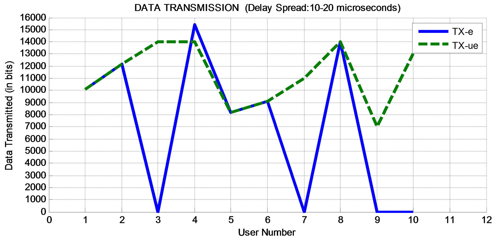
Figure 8. Data transmission (delay spread: 10 - 20 µs).
delay spread of 12 µs for this particular user. Given the number of OFDM symbols per sub-frame, the transmission of user Number 3 clearly favoured extended CP insertions. Conversely, user Number 8 with randomly generated delay spread of 26 µs transmitted data using the proposed ultra extended CP while same user was unable to successfully transmit any bit using extended CP.
In Figure 7, the proposed ultra extended CP generally leads to higher data transmission than the existing extended CP. Similar explanations go for results presented in Figure 8.
Upon completion of the simulation runs, the total bits transmitted by the ten users using the proposed ultra extended CP was generally more than bits transmitted using the extended CP. For example, with the delay spread in the range 4 - 30 µs, 67 kilobits and 112 kilobits were transmitted by the ten users using the ultra extended and extended CP respectively. Similarly, with the delay spread in the range 5 - 33 µs, 56 kilobits and 112 kilobits were transmitted by the ten users using the extended and ultra extended CP respectively. Moreover, with the delay spread in the range 10 - 20 µs, 69 kilobits and 114 kilobits were transmitted by the ten users using the extended and ultra extended CP respectively. Clearly, the proposed ultra extended CP provides a basis for wider transmission coverage as it can effectively address the problem of signal corruption due to longer delay spread.
It should be noted that longer CP may be beneficial in specific environments with extensive delay spread; for example in future telecommunication systems with large cells (or wider cell coverage area).
5. Conclusions
When transmitted signals arrive at the receiver by more than one path of different length, the received signals are staggered in time; this is multipath propagation. To mitigate the effect of dispersed channel distortion caused by random channel delay spreads, Cyclic Prefix (CP) is introduced to eliminate Inter-Symbol Interference (ISI). In this paper, a new approach for mitigating the effect of multipath propagation was proposed. This new approach, called the “ultra extended” CP, improved the capability of the existing extended CP. Even though the number of OFDM symbols per slot was reduced from 6 to 5, the shortfall in bits transmission was removed by the capability offered by the ultra extended CP to effectively transmit data when delay spread was beyond 16.67 µs. It was assumed that channel performance was not constrained by noise but rather signal corruption as a result of channel time dispersion caused by longer delay spread. Furthermore, it was noted that longer CP may be beneficial in specific environments with extensive delay spread; for example in future telecommunication systems with large cells (or wider cell coverage area). Moreover, the energy needed for re-transmission of corrupted signals for the case of extended CP, caused by longer delay spreads, justifies the additional energy overhead of longer CP. The efficacy of the proposed CP was tested under different scenarios via simulation. The results obtained showed that the proposed ultra extended CP can indeed be implemented in the design of future telecommunication systems to address problems of signal corruption due to longer delay spread.
Future research work will focus on improvement of transmission efficiency.