FDM 3D-Print on Thermoplastic Polyurethane (TPU) with Different Process Parameters Using Gyroid and Zigzag Infill Patterns ()

1. Introduction
Thermoplastic Polyurethane (TPU) is a versatile and flexible thermoplastic elastomer that has gained popularity in various industries due to its unique combination of properties. When used in Fused Deposition Modelling (FDM) 3D printing [1] [2] . In the former researches different infill patterns are used but they did not achieve good mechanical properties [3] . TPU offers exciting opportunities for creating flexible and durable parts with intricate designs. Let’s delve into an introduction to TPU material and its use in FDM 3D printing. Thermoplastic Polyurethane (TPU) is a type of elastomer that falls within the broader category of thermoplastic elastomers (TPEs). It is known for its excellent flexibility, high elongation, good abrasion resistance, and resistance to oils and greases. TPU can be tailored to exhibit a range of hardness levels, from very soft and rubber-like to more rigid and plastic-like [3] .
1.1. Advantages of Printing with TPU
Flexibility: TPU is highly flexible and can be used to produce parts with rubber-like qualities. This makes it suitable for creating objects that need to bend, stretch, or compress.
Durable and Resilient: TPU parts have good abrasion resistance and durability, making them suitable for applications that require wear resistance and impact absorption.
Elasticity: TPU exhibits high elongation and can be stretched without permanently deforming, which is beneficial for producing functional prototypes, gaskets, seals, and other elastic components.
Ease of Processing: TPU is relatively easy to 3D print compared to some other flexible materials, thanks to its compatibility with FDM printers [4] [5] [6] .
1.2. Considerations for Printing with TPU
Printer Compatibility: TPU can be more challenging to print than rigid filaments due to its flexibility and potential for filament tangling. Ensure that your FDM printer is compatible with flexible materials and has the necessary features, such as a direct drive extruder or a flexible filament guide.
Print Settings: Adjusting print settings is crucial when working with TPU. This includes nozzle temperature, print speed, layer height, and infill density. Printing too quickly or with improper settings can result in poor layer adhesion and deformation.
Bed Adhesion: Adequate bed adhesion is essential to prevent warping or detachment during printing. Use a heated bed if available and consider using adhesive solutions like glue stick or specialized bed adhesion products.
Retraction: Proper retraction settings help minimize stringing and oozing, common challenges when printing with flexible filaments [5] [7] .
1.3. Applications
TPU’s flexibility and durability make it suitable for various applications, such as:
Footwear: Insoles, shoe components, and prototypes for footwear design.
Functional Prototypes: Gaskets, seals, hinges, and other parts with elastic properties.
Sports Equipment: Grips, handles, padding, and protective gear.
Soft Robotics: Components for robotic systems requiring compliant and flexible parts.
Medical Devices: Prototyping medical devices, prosthetics, and orthotics [8] [6] [9] .
1.4. Future Developments
As 3D printing technology evolves, so does the range of available TPU formulations and materials specifically designed for FDM. Researchers and manufacturers continue to develop new TPU blends with improved properties, ease of printing, and compatibility with a wider range of 3D printers. In conclusion, TPU is a versatile and flexible material that offers exciting possibilities for FDM 3D printing. Its unique combination of properties makes it suitable for a variety of applications where flexibility, durability, and resilience are important. However, successful printing with TPU requires careful consideration of printer compatibility, settings, and techniques to achieve the desired results [6] [9] .
2. Materials and Methods
Thermoplastic polyurethanes (TPU) are macromolecules composed of aliphatic polyether segments with high mobility (called soft segments (SS)) separated by inflexible aromatic groups (called hard segments (HS)) that can organize and crystallize by forming hard domains. TPU are biphasic materials comprised of (more or less semi-) crystalline clusters where HS are aggregated by one to one interactions generating hard domains, distributed in the amorphous phase where chains of SS are intertwined forming soft domains. TPU’s elastomeric properties are provided by such unique organization. TPU properties can be modified based on their nature―the SS to HS ratio and the degree of separation between these two phases [6] . TPU is an excellent biological choice since it is biocompatible and hemocompatible [10] [11] .
The thermodynamic incompatibility of polar hard segments and relatively nonpolar soft segments causes microphase separation in thermoplastic polyurethanes (TPU), which are linear segmented block polymers (Figure 1). The hard
![]()
Figure 1. Thermoplastic Polyurethane (TPU) filament.
segments (HS) of TPU are typically made of diisocyanates and small-molecule chain extenders (like diamines or diols), which give them good mechanical strength [12] [13] . In contrast, the soft segments (SS) are made of oligomeric diols, which give them flexibility and elastic behaviour. As a result, the material’s attributes may be adjusted by adjusting the proportion of soft to hard segments and the structure’s morphologies, which enables the material’s distinctive performance, including outstanding wear resistance, high tensile strength, superior chemical resistance, and machinability. TPU have become a more significant factor in recent years [14] .
2.1. FDM 3D-Printing
Fused Deposition Modelling (FDM) is a widely used 3D printing technology that revolutionized the way objects are manufactured and prototyped. It was developed by Stratasys in the late 1980s and has since become one of the most popular and accessible methods for creating three-dimensional objects [13] [15] .
At its core, FDM operates on the principle of additive manufacturing, where objects are built layer by layer from the bottom up. The process involves the following key steps:
Design: The process begins with a computer-aided design (CAD) model, which serves as the blueprint for the object you want to create (Figure 2). The CAD model is converted into a format that the 3D printer can understand [15] [16] .
Slicing: Slicing software takes the 3D model and “slices” it into numerous thin horizontal layers. This slicing process generates a set of instructions that guide the printer on how to deposit material layer by layer [16] [17] .
Printing: The 3D printer heats a spool of thermoplastic filament to its melting point. The melted material is then extruded through a small nozzle and deposited onto the print bed in the specified pattern (zig-zag and gyroid pattern) based on the sliced instructions. The material quickly cools and solidifies, bonding with the layer below.
Layer-by-Layer Construction: The printer continues to add material layer by layer, gradually building up the object. Each layer fuses with the previous one, resulting in a cohesive and accurate representation of the digital model.
Support Structures: In cases where the object has overhangs or complex geometries, support structures may be printed alongside the main object. These temporary structures help prevent deformation during the printing process and are removed once printing is complete.
Cooling and Solidification: As each layer is deposited, it cools and solidifies almost immediately, ensuring that subsequent layers adhere properly. The build platform may move vertically or horizontally, depending on the specific 3D printer’s design.
Completion and Post-Processing: Once the printing is finished, the object is carefully removed from the print bed. Depending on the material used and the desired finish, post-processing steps such as sanding, painting, or additional treatments may be applied to achieve the desired final appearance and functionality [16] .
FDM 3D printing offers numerous advantages, including affordability, accessibility, and versatility. It supports a wide range of thermoplastic materials, making it suitable for various applications, from rapid prototyping to creating functional end-use parts. While FDM may not provide the same level of detail and precision as some other 3D printing methods, its speed and simplicity have made it a popular choice for hobbyists, educators, and professionals alike. As technology continues to advance, FDM 3D printing continues to evolve, contributing to innovative solutions across industries [5] [18] .
Manufacturing Test Samples
The FDM 3d print TPU samples are manufactured using the creality ender3V2 FDM printer (Figure 3) with the 2 different infill patterns (zig-zag, gyroid) and
![]()
Figure 3. FDM Creality Ender 3V2 3D-Printer.
3 different print parameters. The 3D printer parameters set in the study were the following: 0.2 mm layer thickness and 100% infill for both infill patterns, and the print parameters are as followed for both infill patterns are same: 235˚C, 245˚C, 255˚C extrusion temperature, 50˚C, 55˚C, 60˚C bed temperatures and 40 mm/s, 30 mm/s, 20 mm/s printing speed respectively (Table 1).
All prints were created with zig-zag and gyroid infill patterns using a Creality Ender 3V2 3D printer with the Prusa slicer slicing software. The filament is made of thermoplastic polyurethane and has a 1.75 mm diameter, 1.21 g/cm3 density, and a recommended melting temperature of 60˚C. During the printing process, the following process parameters were held constant: Layer thickness is 0.2 mm, infill density is 100%, shells are two, and tip/bottom layers are two. The rectilinear lines and calibration cubes were measured and their quality was determined visually. The parameters listed below produced the best results: For the first layers of all prints, a bed temperature of 50˚C and a nozzle temperature of 240˚C were used, with three different printing speeds of 20 mms, 30 mms, and 40 mm/s.
The above printing parameters were used to print the test samples for the tensile (ISO 178) and flexural tests (ISO 178). Tensile and flexural specimens with gyroid and zig-zag infill patterns (Figure 4(a) & Figure 4(b)).
2.2. Mechanical Tests
2.2.1. Tensile Test
Tensile testing, often known as tension testing, is a fundamental mechanical test used to measure the mechanical properties of materials under axial force (Figure 5). It provides significant insights into a material’s behaviour when subjected to stretching forces, which is essential for engineering design, quality control,
![]()
Table 1. Tested parameter settings for 3D printing TPU samples.
and material selection in industries such as aerospace, automotive, manufacturing, and construction. This material seeks to provide a detailed description of the tensile testing procedure, its importance, and the standard technique used to conduct such tests [11] [13] [19] .
Tensile testing is critical for understanding how materials behave to tensile forces and for providing data for engineering applications. This test, which adheres to a standardized approach, allows researchers, engineers, and manufacturers to make educated judgments on material selection, design, and quality assurance. Accurate documentation of the tensile testing process improves reproducibility of results and advances material science and engineering standards [14] [16] .
2.2.2. Flexural Test
Flexural testing, commonly referred to as bending testing, is a basic mechanical testing technique used to assess the bending behaviour and strength of materials. The performance and structural integrity of different materials, such as metals, polymers, ceramics, and composites, are particularly important to be evaluated using this test [18] . A controlled bending stress is applied to a specimen during the flexural test, causing the material to deform into a curved shape (Figure 6). Engineers and scientists can learn more about a material’s stiffness, elasticity, and ultimate strength in bending situations by measuring the applied force and the resulting deformation.
In order to determine if a material is suitable for a given application, the flexural test is frequently used in the engineering, material science, and industrial sectors. It offers useful information for designing items like beams, bridges, cars, and structural elements that will be subjected to bending or flexural loads. Engineers may choose a material with confidence by having a thorough understanding of its flexural characteristics, thereby ensuring the finished product is safe, dependable, and performs at its best [17] [18] [20] .
The fundamentals of flexural testing, including its types, standards, setup, procedures, and data analysis, will be covered in detail in this document. This documentation’s goal is to give readers the knowledge necessary to perform precise and significant flexural tests on a variety of materials by giving a thorough overview of flexural testing. Understanding flexural testing’s principles and procedures will help you make better decisions and improve the field of material science and engineering, whether you’re a researcher, engineer, student, or business professional.
3. Results and Discussion
3.1. Comparison of Tensile Results
3.1.1. Comparison in Zig-Zag Infill Pattern with Various Print Speeds
According to the findings (Graph 1), a zigzag infill pattern printed at a speed of 40 mm/s with a nozzle temperature of 235˚C and a bed temperature of 50˚C demonstrated a high tensile strength of 50.82 mpa. The tensile strength is lower when compared to the print parameters of print speed 20 mm/s, 255˚C nozzle temperature, and 60˚C bed temperature (22.1 mpa) and 30 mm/s, 245˚C nozzle temperature, and 55˚C bed temperature (28.12 mpa).
3.1.2. Comparison in Gyroid Infill Pattern with Various Print Speeds
According to the findings (Graph 2), a gyroid infill pattern printed at a speed of 20 mm/s with a nozzle temperature of 255˚C and a bed temperature of 60˚C demonstrated a high tensile strength of 34.9 mpa. The tensile strength is lower
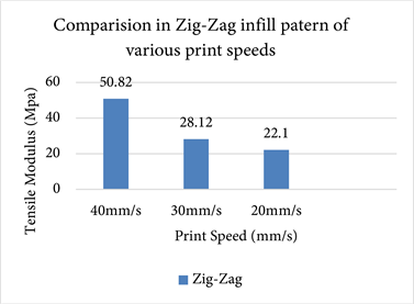
Graph 1. Tensile strengths of a zig-zag infill samples.

Graph 2. Tensile strengths of a gyroid infill samples.
when compared to the print parameters of print speed 40 mm/s, 235˚C nozzle temperature, and 50˚C bed temperature (20.1 mpa) and 30 mm/s, 245˚C nozzle temperature, and 55˚C bed temperature (21.3 mpa).
3.1.3. Comparison between Zig-Zag & Gyroid Infills with Various Print Speeds
Infill Pattern and Tensile Strength: In both sets of findings (Graph 3), the zigzag infill pattern demonstrated a higher tensile strength compared to the gyroid infill pattern. The zigzag pattern exhibited a tensile strength of 50.82 MPa, while the gyroid pattern had a tensile strength of 34.9 MPa.
Print Speed: The zigzag pattern (40 mm/s) was printed at double the speed of the gyroid pattern (20 mm/s) in Findings 1. Despite the higher print speed, the zigzag pattern still showed a superior tensile strength.
Temperature Considerations: The nozzle and bed temperatures for the zigzag
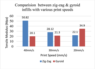
Graph 3. Tensile strengths of a zig-zag & gyroid infill samples.
pattern (235˚C and 50˚C) were lower than those for the gyroid pattern (255˚C and 60˚C). Despite the lower temperatures, the zigzag pattern achieved a higher tensile strength, indicating that other factors, such as pattern geometry and material properties, might have contributed to the observed differences.
When comparing the specific parameter combinations with the highest tensile strengths in both sets of findings, the zigzag pattern (40 mm/s, 235˚C nozzle, 50˚C bed) outperformed the gyroid pattern (20 mm/s, 255˚C nozzle, 60˚C bed) by a significant margin (50.82 MPa vs. 34.9 MPa). These comparisons suggest that the zigzag infill pattern and the specific parameter combination used in Findings 2 resulted in superior tensile strength compared to the gyroid infill pattern and the parameter combination in Findings 1, even though the zigzag pattern was printed at a higher speed and lower temperatures.
3.2. Comparison of Flexural Results
3.2.1. Comparison in Zig-Zag Infill Pattern with Various Print Speeds
According to the findings (Graph 4), a zig-zag infill pattern printed at a speed of 20 mm/s with a nozzle temperature of 255˚C and a bed temperature of 60˚C demonstrated a high flexural strength of 50.2 mpa. The flexural strength is lower when compared to the print parameters of print speed 40 mm/s, 235˚C nozzle temperature, and 50˚C bed temperature (20 mpa) and 30 mm/s, 245˚C nozzle temperature, and 55˚C bed temperature (33.3 mpa).
3.2.2. Comparison in Gyroid Infill Pattern with Various Print Speeds
According to the findings (Graph 5), a gyroid infill pattern printed at a speed of 20 mm/s with a nozzle temperature of 255˚C and a bed temperature of 60˚C demonstrated a high flexural strength of 39.9 mpa. The flexural strength is lower when compared to the print parameters of print speed 40 mm/s, 235˚C nozzle temperature, and 50˚C bed temperature (26 mpa) and 30 mm/s, 245˚C nozzle temperature, and 55˚C bed temperature (27.2 mpa).
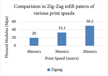
Graph 4. Flexural strengths of a zig-zag infill samples.
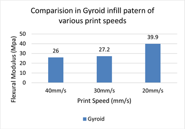
Graph 5. Flexural strengths of a gyroid infill samples.
3.2.3. Comparison between Zig-Zag & Gyroid Infills with Various Print Speeds
Infill Pattern and Flexural Strength: In both sets of findings (Graph 6), the zig-zag infill pattern demonstrated a higher flexural strength compared to the gyroid infill pattern. The zig-zag pattern exhibited a flexural strength of 50.2 MPa, while the gyroid pattern had a flexural strength of 39.9 MPa.
Print Speed and Flexural Strength: The zig-zag and gyroid patterns were printed at the same speed (20 mm/s). Despite the similarity in print speed, the zig-zag pattern displayed higher flexural strength in both sets of findings.
Temperature Considerations: The nozzle and bed temperatures were identical for both patterns (255˚C and 60˚C). Therefore, the observed differences in flexural strength are likely attributed to the inherent characteristics of the infill patterns themselves rather than temperature variations.
When comparing the specific parameter combinations with the highest flexural strengths in both sets of findings, the zig-zag pattern (20 mm/s, 255˚C

Graph 6. Flexural strengths of a zig-zag & gyroid infill samples.
nozzle, 60˚C bed) outperformed the gyroid pattern (20 mm/s, 255˚C nozzle, 60˚C bed) in terms of flexural strength (50.2 MPa vs. 39.9 MPa).
These comparisons suggest that, in the context of these specific parameter combinations, the zig-zag infill pattern consistently exhibited higher flexural strength compared to the gyroid infill pattern, despite both patterns being printed at the same speed and temperatures.
4. Conclusions
In conclusion, this study has provided valuable insights into the intricate relationship between process parameters, infill patterns, and the mechanical performance of 3D-printed objects using the Fused Deposition Modelling (FDM) technique. Through systematic experimentation and mechanical testing, it has been demonstrated that the selection of infill pattern, along with variations in critical process parameters such as nozzle temperature, print speed, and bed temperature, significantly influences the mechanical behaviour of printed specimens.
The research highlighted the pivotal role of infill pattern in determining the mechanical characteristics of 3D-printed objects. Specifically, the zig-zag infill pattern consistently exhibited superior tensile and flexural strengths when compared to the gyroid pattern. This pattern’s performance remained impressive even when printed at higher speeds and lower temperatures. Moreover, the investigation underscored the complex interplay between process parameters and mechanical properties, revealing that optimized combinations of nozzle temperature, print speed, and bed temperature can enhance the strength and durability of printed objects.
Looking ahead, this study opens avenues for future research in the field of FDM 3D printing. The identified relationships between process parameters, infill patterns, and mechanical performance can serve as a foundation for exploring other infill patterns and their interactions with diverse materials. The influence of additional parameters, such as layer height and extrusion width, could also be investigated to further refine the understanding of their effects on mechanical properties. Additionally, this research could be extended to real-world applications, investigating how the findings can be applied to design more resilient and robust 3D-printed components across various industries.
The future scope of this research lies in the exploration of a broader range of infill patterns and materials to comprehensively understand their combined effects on mechanical properties. Investigating the impact of finer process parameters, such as layer height and extrusion width, could provide a more nuanced understanding of their contributions. Furthermore, the application of the findings to specific industries, such as aerospace, automotive, and healthcare, could lead to the development of tailored 3D-printed components with enhanced mechanical performance. Collaborative efforts between material scientists, engineers, and designers could help optimize the symbiotic relationship between process parameters, infill patterns, and mechanical characteristics, ultimately advancing the capabilities and reliability of FDM 3D printing technology.