Energy Efficiency Assessment of Building Wall with PCM Layers in the Hot Summer Locations ()
1. Introduction
PCM (phase-change) materials are a vast challenge among novel building materials. In the diversity of roles, they are known for: 1) buffering and shifting of peak thermal loads of walls if they are integral parts of walls; 2) regulating the net thermal energy transfer among walls and surroundings; 3) substituting HVAC (heating, ventilation, and air conditioning) system (reducing heating and cooling loads of a residence). There has been substantial scientific research in the past, on specific designs of building elements with embedded PCM materials and their influence on exterior-interior temperature fluctuations. Cristina Cornaro et al. [1] tested a custom software tool named “PCM wall” which was simulated in IDA Indoor Climate and Energy software for two office building models. The authors investigated the envelope characteristics of two building models, (STD building) which complied with the Italian norm 192/2005, and the other which complied with the minimum requirements of 25th June 2015 (NZEB building). Additionally, the STD building model equipped respectively with three different kinds of PCM panels, with different melting points, (SP21E, SP24E, SP26E) was simulated in three Italian cities to verify potential improvements in energy savings in comparison to the two cited building models. It was found that PCM with a 21˚C melting point has the best annual energy-saving performance in all cities. Barzin et al. [2] presented an experimental investigation on the benefits of using PCM in the underfloor heating system, by comparing two small huts of 2.63 m × 2.64 m × 2.64 m, built at Tamaki Campus of University of Auckland, New Zealand. The first hut was finished with an ordinary gypsum board while the second one included PCM boards on the floor (PCM: paraffin, melting range 27˚C - 29˚C), and PCM boards called Energain on the walls and ceiling (PCM: paraffin, melting range 21.7˚C). The article with a similar theme (usage of PCMs in underfloor heating; walls and ceiling) signed by Paul Devaux and MM Farid [3], proved both energy and cost savings of 32% and 42% respectively with two different PCMs implemented, one with higher and other with a lower melting point. Articles [4] [5] also neatly contributed to the testimony of PCM materials’ role in passive heating and cooling, since they were implemented in different system designs inside the building.
A high percentage of scientific articles were addressed particularly on PCM integration in building walls and the quantity of papers has increased over the latter several years. Reference cited as [6], showed the thermal characterization of the housing wall systems where a few thermodynamical determinants such as temperature-time lag values were presented for every single wall in the object. Furthermore, different manners in which PCM materials can be used in building restoration, as well as the influence of fenestration on the thermal behavior of buildings, were discussed in [7].
The findings in this manuscript were related to the optimal position of the PCM layer due to the thermal comfort; the adequate thickness of the PCM-integrated wall; honeycomb or hollow-core thermal insulations; the general PCM effect and the monthly monetary savings for the PCM-integrated wall.
2. The Experimental Modulus
The experimental modulus was set up in the technical laboratory at the Department of Energy and Power Engineering of the University of Science and Technology, in Changsha, China. The gypsum walls were subjected to the transient heat mode, by altering the input heat quantity. Transient heat mode was beforehand determined, according to the different solar radiation, characteristic for the Chinese town, Changsha. The bounds of the solar radiation, i.e. heat flux were up to 240 W/m2.
The emphasis of this research was on thermocouples clutched into the styrofoam layers, one filled with PCM spheres and the other perforated with holes in the size of PCM spheres, and their thermal ducts. Supervised thermal ducts, located in styrofoam layers, one with PCM and the other with holes, in electronic data processing were numbered 218 and 220. These styrofoam layers changed their position simultaneously from 1 to 5 and the other thermal insulation, 4 styrofoam layers were whole.
In Figure below, was given the layout of 1) styrofoam insulation layer filled with PCM spheres; 2) styrofoam insulation layer perforated with holes in the size of PCM spheres; 3) inner structure of the gypsum walls (red-styrofoam layer with holes), (blue-styrofoam layer with PCM balls), thin red line—heating foil.
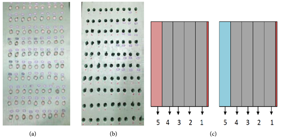
The heating foils were located between the gypsum board and the first styrofoam insulation layer in each gypsum wall model. The position of the heating foils during the experiment was unchangeable. Heating foils had dimensions 500 mm × 1000 mm × 0.37 mm.
Voltage generator, of AC alternating voltage, branded as STG-1000 W was used for electric power supply. By altering the voltage in jumps, i.e. the current through the heating foil, the heat flux was modified, which simulated the extent of solar radiation. The jumps of voltage were predefined from (0 - 228 V), which corresponded to the extent of solar radiation, heat flux from (0 - 240 W/m2).
The gypsum boards, which formed wall models, had dimensions 500 mm × 900 mm × 8 mm with the coefficient of thermal conductivity λg = k = 0.20 W/m˚C and thermal resistance Rg = dg/λg = 0.04 m2˚C/W. Styrofoam insulation panels had dimensions 500 mm × 900 mm × 17 mm with the coefficient of thermal conductivity λs = 0.030 W/m˚C, whilst the thermal resistance was Rs = ds/λs = 0.017/0.030 = 0.57 m2˚C/W. Styrofoam insulation layers were compressed with metal clamps in each gypsum wall model so that there was not any air gap between the layers.
PCM spheres were made of spherical, polymer husks, i.e. husks of high-density polyethylene, hermetically closed. The coefficient of thermal conductivity of PCM polymer spherical husks was λPCM = k = 0.32 W/m˚C. In the PCM spheres, was injected organic phase-change material, paraffin Rubitherm, marked as OP28E.
The used thermocouples, clenched into the styrofoam layers, with PCM spheres and holes, were connected with the instrument for the digital data registration, Data Logger Agilent 34972A LXI, which was merged to the computer.
Ultimately, the transient heat mode simulated the 24 h change of ambient temperature, i.e. the shift of day and night.
3. Indoor Temperatures of Thermal Comfort for Ordinary and Passive Households
Temperature leveling, acclimating, or tuning up of a thermostat is essential for indoor thermal comfort. Generally, thermal comfort is accomplished by: boosted building envelope, insulation panels, and coatings, air heat exchangers that are buried under the ground with a cap or shutter above the ground, heat pumps, low-consumption heating boilers, photovoltaic modules, two-layered or three-layered glazed windows filled with noble gases, i.e. krypton, argon, xenon, etc.
Since the overpassing of 25˚C in the building interior means overheating, (during relatively both seasons), the Passive House Planning Package recommends not to exceed 25˚C for more than 10% of hours annually [8]. The low-energy households must be primarily accustomed to the passive ventilation strategies (passive heating, passive cooling) and then supported by HVAC (active ventilation systems).
Many construction design guidelines claim that the optimal temperature difference between the window pane (glazed surface) and the room interior should be 3˚C. So, if the temperature of the inner glazed surface is 17˚C, the room temperature should be 20˚C [9]. The window panes are hence coated with metal oxides, protective foils that reject the multitude of sunrays during summertime and retain the warmth during wintertime. Lifting of room temperature for 1˚C requires even 2% more (spent) thermal energy. Invoking that the energy-efficient design ought to be at the same time cost-effective design, the British Passivhaus Trust recommends that the ‘‘windows on a south wall’’ occupy at most 25% of the outer wall surface. That could be adequate for a daylight intake, except for rooms deeply inside the household.
Tenants’ testimonials from the hot-arid climatic zone of Ethiopia speak up in favor of traditional building techniques, where according to ASHRAE standards, 88% of tenants in traditional households were satisfied with indoor thermal ambiance [10]. Habitually, elder people (tenants) prefer warmer interiors, up to 25˚C, 26˚C or even greater in the winter, because of their lowered mobility rate and blood vessels.
General provisions on energy-efficient design indicate that the following temperature ranges of indoor thermal comfort for ordinary and passive households are:
• 20˚C - 24˚C, going up to 25˚C, for an ordinary household, (on average insulated) in the winter;
• 18˚C - 22˚C for an ordinary household, (on average insulated) in the summer;
• 20˚C - 22˚C for a passive household, (extremely insulated) in the winter;
• 18˚C - 20˚C for a passive household, (extremely insulated) in the summer.
The general room temperature range in both seasons can be taken as the range from 20˚C to 25˚C.
Thermal comfort means improvement or an upgrade of living standards, which tenants tend to achieve with: ventilated facades, free-standing balconies, Trombe wall, south wall glazing, glass panorama, thicker thermal insulation, newest insulation materials such as PCM materials, etc.
4. The Changeable Position of PCM Insulation Layers within Gypsum Wall in the Hot Summer Locations–Experimental Results
Transient heat mode is distinctive by its short-lived nature, i.e. short-lived gusts of heat. It suits unrealistic conditions, (more scientific and metering conditions), representing hourly rates or even shorter rates of heat emission. In the analyzed transient heat mode, there was no continuous maintenance of temperature magnitude and so there was none of the striking latent heat storage (steep nature of the graphs). Since the temperature raises in gusts, the only stored heat (theoretically) during the melting phase of PCM spheres, in styrofoam insulation, was sensible. The heat flux raises in the jumps from 0 W/m2 to 240 W/m2, from point A to point E, (0 W/m2, 120 W/m2, 160 W/m2, 200 W/m2 and 240 W/m2) and vice versa from point E to point J, i.e. to 0 (Table 1).
![]()
Table 1. The heating up and cooling down of PCM spheres and holes in insulation layers, due to the changeable voltage on voltage regulator and changeable thermal flux.
By tracking the temperatures in the styrofoam insulation layers, one filled with PCM spheres and other with holes in the size of PCM spheres, positioned next to heating foil, as 1 insulation layer, it was concluded that insulation layer with holes has the slightly higher temperature than insulation layer with PCM spheres. This effect appears due to the natural air convection in the holes of the styrofoam insulation layer, which raises the heat flow. The honeycomb or hollow-core thermal insulations are considerably rare in the praxis, rather exist as some insulation foils or bands. Therefore, the orange line in the graphs was not so important. Following the blue line, representing the styrofoam insulation layer filled with PCM spheres, the thermal comfort zone, from 20˚C to 25˚C, (general room temperature range) was set up. In this thermal comfort zone, the HVAC was off and the effect of PCM spheres was ponderable (mensurable).
Thermal comfort is equal to the long-lasting PCM effect. In electronic data sets, which were processed into excel sheets, one part of the curve belonged to the melting phase of PCM spheres and the other to the solidification phase of PCM spheres. In Figure 1 below, the total duration of the thermal comfort, (PCM effect) is approximately 11 hours ≈ 11 hours 3 minutes. The thermal comfort is much more viable in the other half of the day, during the night. The PCM spheres, positioned in the first styrofoam insulation layer, next to the heating foil, absorb very lightly the heat, in the morning, for 1 hour and 27 minutes, within the temperature limits of thermal comfort. In the other half of the day, on the shift of night and dawn, the PCM effect lasted 9 hours and 36 minutes, which implied the much longer discharge of previously-stored latent heat. These data can be read from Figure 1 and the enclosed Table 2.
![]()
Figure 1. The styrofoam layers, one filled with PCM spheres and the other with holes, during the transient heat mode in the summer, at position 1 in the gypsum wall.
(a) ![]() (b)
(b) ![]()
Table 2. The time intervals of a thermal comfort zone, while HVAC is off, from 20˚C to 25˚C for (a) PCM insulation layer at position 1; (b) insulation layer with holes at position 1.
For the secondly positioned PCM insulation layer in the gypsum wall, (blue line on Figure 2), the thermal comfort lasted a bit longer than in a previous case. The total duration of the thermal comfort (PCM effect) was 12 hours and 13 minutes. The discharge of the stored latent heat lasted longer than in the first layer, i.e. 10 hours and 30 minutes. This is also a relatively favorable position of the PCM insulation layer, with no so superior amenities for the occupants. In this position of the PCM layer, PCM spheres still do not show their maximum effect related to thermal comfort. Data regarding HVAC activity are given in Table 3.
For the styrofoam insulation layers, filled with PCM spheres and holes, positioned as 3, the thermal comfort lasted the longest time, 14 hours and 43 minutes (Figure 3 and Table 4). From the standpoint of thermal comfort and heat flow, this is the optimal position of PCM spheres in the gypsum wall. Considering that in this experimental research were 5 styrofoam layers in total, PCM spheres in this position were in the middle of the gypsum wall.
The PCM integrated into the wall, congested with a lot of thermal insulation before that, is not a good practical solution. Layers of thermal insulation because of its thermal resistances have a buffer effect on a heat flow and therefore the PCM effect is incomplete. That means the melting and solidification phases are barely feasible and the thermal comfort (originating from PCM spheres) is not full. Lined up as a 4. thermal insulation layer, PCM spheres provide the thermal comfort of 10 hours and 17 minutes, which is shorter than in previous cases (Figure 4 and Table 5).
Lined up as a 5. thermal insulation layer, PCM spheres accomplished the maximum temperature of 21.9˚C, which is not the utmost temperature of the specified thermal comfort range. The styrofoam layer with holes accomplished the maximum temperature of 22.1˚C. This happened due to the thermal resistances of the 4 prior lined up styrofoam layers, which decelerated the heat flow from the heating foil. In such a position, PCM spheres enabled the thermal comfort of a total of 8 hours and 49 minutes, which is the shortest duration of thermal comfort (Figure 5 and Table 6). Hence, such position of the PCM
(a) ![]() (b)
(b) ![]()
Table 3. The time intervals of a thermal comfort zone, while HVAC is off, from 20˚C to 25˚C for (a) PCM insulation layer at position 2; (b) insulation layer with holes at position 2.
(a) ![]() (b)
(b) ![]()
Table 4. The time intervals of a thermal comfort zone, while HVAC is off, from 20˚C to 25˚C for (a) PCM insulation layer at position 3; (b) insulation layer with holes at position 3.
(a) ![]() (b)
(b) ![]()
Table 5. The time intervals of a thermal comfort zone, while HVAC is off, from 20˚C to 25˚C for (a) PCM insulation layer at position 4; (b) for insulation layer with holes at position 4.
thermal insulation layer is the worst position in the gypsum wall, among specimens of layering.
(a) ![]() (b)
(b) ![]()
Table 6. The time intervals of a thermal comfort zone, while HVAC is off, from 20˚C to 25˚C for (a) PCM insulation layer at position 5; (b) insulation layer with holes at position 5.
![]()
Figure 2. The styrofoam layers, one filled with PCM spheres and the other with holes, during the transient heat mode in the summer, at position 2 in the gypsum wall.
![]()
Figure 3. The styrofoam layers, one filled with PCM spheres and the other with holes, during the transient heat mode in the summer, at position 3 in the gypsum wall.
![]()
Figure 4. The styrofoam layers, one filled with PCM spheres and the other with holes, during the transient heat mode in the summer, at position 4 in the gypsum wall.
![]()
Figure 5. The styrofoam layers, one filled with PCM spheres and the other with holes, during the transient heat mode in the summer, at position 5 in the gypsum wall.
5. Energy Efficiency Analysis of PCM Insulation Layer and Insulation Layer with Holes
Based on the results given in Tables 2-6 and Figures 1-6, were presented the time intervals of a thermal comfort zone (from 20˚C to 25˚C) in which HVAC is off. Insulation layers with PCM spheres and holes were placed at different positions 1 - 5.
It is obvious from Figure 6. That the HVAC system (heating and cooling) is switched off for the longest time (i.e. the shortest time is switched on) when the layer with PCM spheres is in the 3 position. From the aspect of energy efficiency, this is the optimal position of the layer with incorporated PCM material. For the 3 position of the layer with PCM spheres, the HVAC ON time for 24 hours is:
![]()
Figure 6. Dependence HVAC OFF on insulation layer (with PCM balls and holes) position.
So, for the layer with PCM spheres, at position 3, this time is:
HVAC ON (h) with PCM = 9 h 17'
HVAC ON (h) with HOLES = 21 h 37'
The HVAC system for the thermal insulation with PCM spheres, within 24 h, will work shorter for the period of ∆t = 12 h 20' = 12.33 h, relative to the thermal insulation with holes.
Taking the average price of 1 KWh of approximately 0.05 $ per 1 KWh and assuming that HVAC of electric power, P = 3 KWh is used for heating and cooling (corresponding to the electric power for a space of about 25 m2), the obtained monetary savings within 24 h when using the third layer of PCM spheres relative to the third layer with holes are:
(1)
For a period of 30 days, that monetary saving amounts to:
These are significant monetary savings at the level of months and years, so it is concluded that the financial investment in the reconstruction of envelopes of lightweight buildings and the incorporation of PCM materials into the envelope, in the areas of hot summer locations pay off very quickly. Also, in hot summer locations, it is financially viable and justified to build new buildings with PCM-incorporated envelopes (ex. encapsulated PCM into polymer spheres in concrete, ...).
6. Conclusion
In this manuscript, the principal issue was analyzed the thermal comfort evoked by the PCM effect. Thermal comfort is equal or depends on the long-lasting PCM effect. From the standpoint of thermal comfort and heat flow, the optimal position of PCM spheres in the gypsum wall was found to be third. In such a position, the thermal comfort lasted 14 hours and 43 minutes out of 24 hours. Among the specimens of layering, PCM spheres in the third position occupied the middle of the gypsum wall. One of the discoveries of this manuscript was that the total thickness of the PCM-integrated wall should not be very (too) thick. In this experimental research, the fourth and fifth insulation layers were redundant. The real PCM effect lasted upon the 3 layers. The PCM-integrated wall should not be very congested with thermal insulation (thermal insulation layers). The honeycomb or hollow-core thermal insulations should be avoided to put alone, because of natural air convection in them, which raises the heat flow. Financial investments in the building PCM-incorporated envelopes, whether it is the reconstruction of old or the construction of new buildings, were justified, especially in the hot summer locations.